12
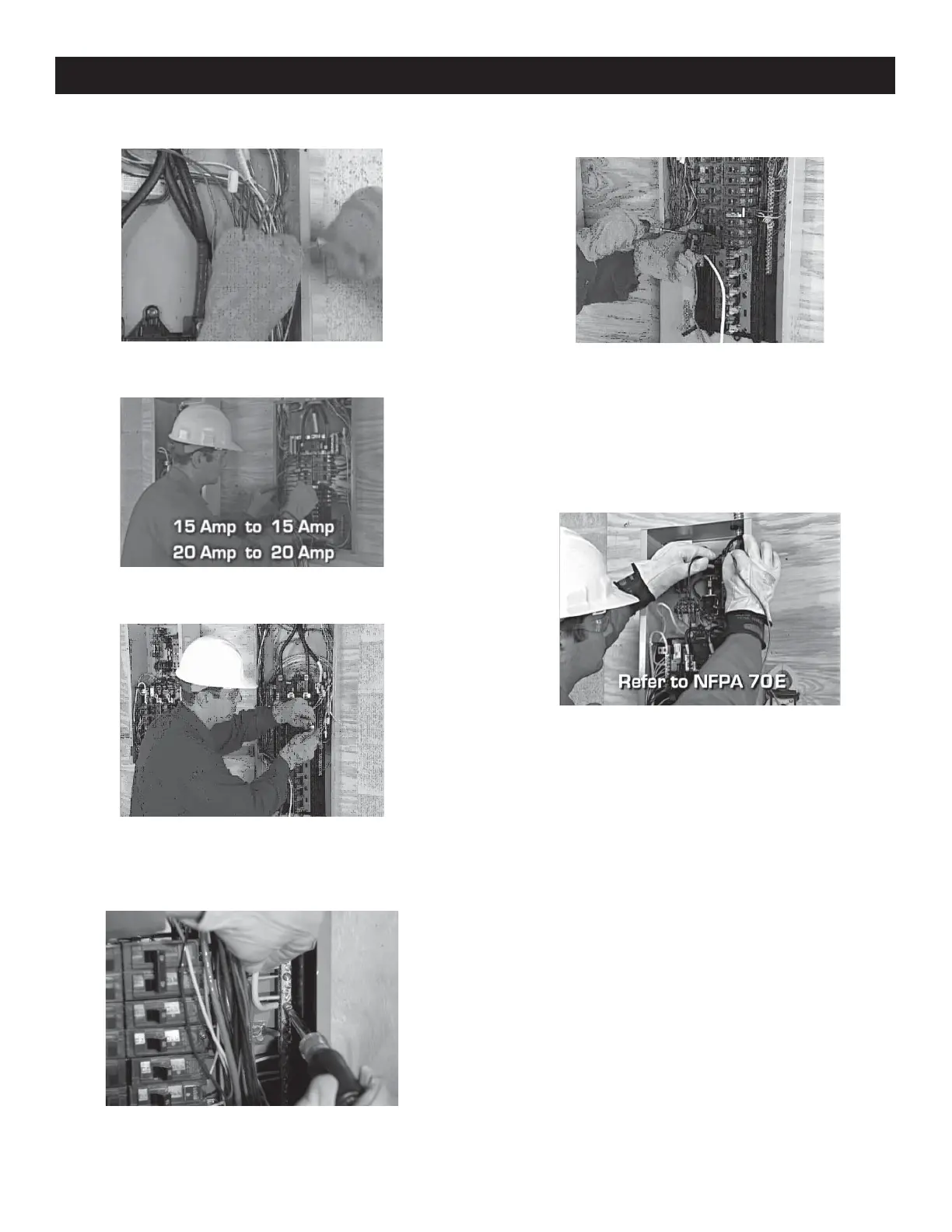
7. Choose a circuit to be backed up and remove the power lead
from the breaker.
8. Using UL Listed wire nuts, reconnect the power lead to a
matching breaker in the transfer switch.
9. Make sure each circuit moved is protected by the same
size breaker in the transfer switch. 15 Amp circuits must be
connected to 15 Amp breakers and 20 Amp circuits to 20
Amp breakers.
10. Connect the provided large neutral to the neutral bar in the
distribution panel.
11. Install a 2-pole breaker in the distribution panel to protect
the transfer switch. The required amp rating of the breaker
depends on which transfer switch is used. Pre-wired load
center switches the breaker cannot exceed 70 Amps. This
breaker must be compatible with the existing electrical
distribution panel.
Install the breaker in two adjacent empty slots (one above the
other) in the main panel.
12. When all priority circuits have been moved to the transfer
switch, close the main breaker to restore utility power and
make sure utility voltage at the transfer switch is correct.
Refer to NFPA 70-E for the safety equipment required when
working inside a live transfer switch.
Appendix A
 Loading...


