Table of Contents
Generac
®
Power Systems, Inc. 1
Safety Rules ......................................Inside Front Cover-1
Section 1 — General Information....................................2
1.1 Introduction ............................................................2
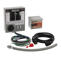
1.2 Equipment Description ..........................................2
1.3 Transfer Mechanism................................................3
1.4 Ratings — Data Plate ..............................................3
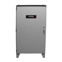
1.5 Panel Board Enclosure ............................................4
1.6 Safe Use of Panel Board ..........................................4
Section 2 — Installation ....................................................4
2.1 Introduction to Installation......................................4
2.2 Unpacking ..............................................................4
2.3 Mounting ................................................................4
2.4 Connecting Power Source and Load Lines ..............4
2.5 Connecting Start Circuit Wires ................................5
Section 3 — Operation ......................................................6
3.1 Functional Tests & Adjustments ..............................6
3.2 Manual Operation....................................................6
3.3 Voltage Checks ........................................................7
3.4 Electrical Operation ................................................8
3.5 Main Contacts at Normal (Utility) ............................9
3.6 Main Contacts at Neutral ........................................9
3.7 Main Contacts at Standby (Emergency) ..................9
3.8 Switches and Advisory Lamps ................................9
3.9 Source Available LED ..............................................9
3.10 Switch Position LED................................................9
Section 4 – Maintenance ................................................10
4.1 Operate Transfer Switch........................................10
4.2 Clean and Inspect Transfer Switch........................10
4.3 Lubrication............................................................10
4.4 Main Current Carrying Contacts............................10
Section 5 – Notes..............................................................11
Section 6 – Installation Diagram ..................................12
Section 7 – Electrical Data..............................................14
Section 8 – Exploded Views & Parts Lists ..................18
Section 9 – Warranty........................................Back Cover
• Because jewelry conducts electricity, wearing it
may cause dangerous electrical shock. Remove all
jewelry (such as rings, watches, bracelets, etc.)
before working on this equipment.
• If working on this equipment while standing on
metal or concrete, place insulative mats over a dry
wood platform. Work on this equipment only while
standing on such insulative mats.
• Never work on this equipment while physically or
mentally fatigued.
• Keep the transfer switch enclosure door closed and
bolted at all times. Only qualified personnel
should be permitted access to the switch interior.
• In case of an accident caused by electric shock,
immediately shut down the source of electrical
power. If this is not possible, attempt to free the
victim from the live conductor but AVOID DIRECT
CONTACT WITH THE VICTIM. Use a nonconduct-
ing implement, such as a dry rope or board, to free
the victim from the live conductor. If the victim is
unconscious, apply first aid and get immediate
medical help.
• When an automatic transfer switch is installed for
a standby generator set, the generator engine may
crank and start at any time without warning. To
avoid possible injury that might be caused by such
sudden start-ups, the system’s automatic start cir-
cuit must be disabled before working on or around
the generator or transfer switch. For that purpose,
a SAFETY DISCONNECT is provided inside the
transfer switch. Always set that switch to its MAN-
UAL position before working on the equipment.
Then place a “DO NOT OPERATE” tag on the
transfer switch and on the generator.