Do you have a question about the Generac Power Systems TTS Series and is the answer not in the manual?
Introduces the Generac product and emphasizes reading the manual thoroughly for safe operation.
Provides general safety rules and defines hazard alert symbols (DANGER, WARNING, CAUTION, NOTE).
Explains hazard symbols like DANGER, WARNING, CAUTION, and associated safety messages.
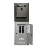
Instructions for unpacking the ILC and overview of its components.
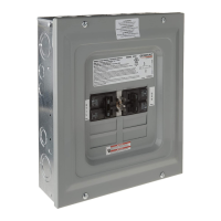
Explains service disconnect breakers and the panel board structure.
Details the TVSS function, components, and protection modes.
Lists the modes of protection provided by the TVSS.
Specifies surge capacity, suppression levels, and UL recognition.
Describes the TVSS disconnect breaker and status LEDs.
Details the function and ratings of remote alarm contacts for TVSS status.
Explains the ATS function in transferring electrical load between sources.
Details voltage rating, amperage rating, and recommended circuit breakers.
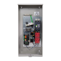
Describes the mechanism housing the main contacts, solenoid, and linkages.
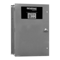
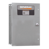
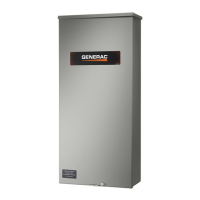
Details ILC ratings, data label importance, and enclosure types.
Emphasizes safety rules, manual consultation, and posting rules.
Explains single-phase use, terminal lugs, and wire ranges.
Notes the data decal and its importance for information and ordering parts.
Lists installation steps including unpacking, mounting, and connecting.
Provides instructions and warnings for mounting the enclosure securely.
Details connecting power source and load leads to the switch.
Describes the 2-pole mechanism, utility, and standby terminals.
Instructions for connecting generator start circuit wires and recommended gauge sizes.
Details connecting wiring to specific terminals for generator starting.
Explains how the battery charger operates and its activation steps.
Describes access to auxiliary contacts for customer accessories and their operation.
Emphasizes careful inspection and functional testing after installation.
Instructions for manually operating the transfer switch, with safety warnings.
Steps to check manual operation to the normal source side.
Steps to check manual operation to the generator source side.
Steps to check manual operation returning to the utility source side.
General instructions for performing voltage checks.
Procedures for checking utility voltage at transfer switch terminals.
Procedures for checking generator voltage and frequency.
Explains contact position and window indicators for normal utility connection.
Describes the neutral position and window indicators.
Explains contact position and window indicators for standby generator connection.
Describes the first step in the automatic transfer sequence.
Explains the delay before starting the generator upon utility failure.
Details the timers for generator run and warmup before load transfer.
Explains sensor checks for standby generator output.
Describes the condition for utility voltage restoration.
Explains the timer preventing premature transfer to utility.
Details the timer for generator cooldown before shutdown.
Provides overview of HMI, including screens and navigation.
Describes the initial screensaver cleared display and overview.
Explains mimic diagram, SYSTEM READY, and EXERCISING indicators.
Lists parameters and default values for sequence settings.
Explains using arrow buttons to navigate HMI screens.
Describes the menu for selecting HMI screens and viewing software versions.
Details settings for inphase, TDN, and system voltage selection.
Covers utility fail/pickup thresholds, delays, and generator load acceptance settings.
Details settings for engine warm-up, cool down, and minimum run timers.
Covers utility frequency settings and thresholds.
Instructions for setting system time, date, and exercise functions.
Details setting exercise day, time, duration, and transfer options.
Accesses test functions like TEST, FAST TEST, RETURN TO NORMAL, and RESET ALARMS.
Explains interpreting input/output status indicators on the HMI.
Shows utility and generator voltage inputs on the HMI screen.
Instructions for calibrating utility and generator voltage inputs on the HMI.
Describes the system status screen for operation and troubleshooting.
Accesses functions like Clean Screen, Contrast, and Calibrate.
Accesses Contrast adjustment popup and other utility functions.
Procedures for testing the generator operation under various load conditions.
Steps to verify the system's proper automatic transfer sequence.
Verifies installation, operation, and educates the end-user.
Recommends operating the transfer switch monthly for testing.
Details yearly cleaning and inspection for damage.
Advises annual checking of main contacts by a service dealer.
Recommends replacing rechargeable lead acid batteries every three years.
States no additional lubrication is usually required, but specifies greases for service.
Describes the document detailing transfer switch data via the secondary communication port.
Lists protocol, baud rate, data bits, parity, and stop bits.
Specifies the Modbus station number.
Provides a register map for available data points and their descriptions.
Shows the first part of the assembly drawing for the ILC.
Shows the second part of the assembly drawing for the ILC.
Shows the third part of the assembly drawing, including a parts list.
Provides the first part of the schematic diagram for the ATS with ILC and Modbus.
Provides the second part of the schematic diagram for the ATS with ILC and Modbus.
Shows the second part of the wiring diagram for the ATS with ILC and Modbus.
Shows the first part of the installation drawing for ILC NEMA 1/3R.
Shows the second part of the installation drawing for ILC NEMA 1/3R.
| Operation | Automatic |
|---|---|
| Dimensions | Varies by model |
| Weight | Varies by model |
| Poles | 2, 3 |
| NEMA Rating | NEMA 3R |
| Voltage Rating | 120/240V, 208V, 480V |
| Enclosure | NEMA 3R |
| Voltage | 120/240V |




 Loading...