General Information
4 Integrated Load Center Owner’s Manual
The LED status indicators can be viewed from the
outside of the enclosure or directly on the TVSS module
with the enclosure door open.
Remote Alarm Contacts
Each TVSS module is equipped with a set of alarm
contacts to indicate the TVSS module protection status,
to an external alarm. This is available as a full set of dry
relay contacts (C, NO, NC). The contact ratings are 3A
250V AC or DC maximum. The contacts are wired to a
three position terminal strip for customer connection.
If the contacts change state, it indicates either a power
failure to the TVSS module or a failure of the TVSS
module.
Automatic Transfer Switch
The automatic transfer switch is used for transferring
critical electrical load from a normal (utility) power source
to a standby (emergency) power source. Transfer of
electrical loads occurs automatically when the normal
power source has failed or is substantially reduced and
the standby source voltage and frequency have reached
an acceptable level. The transfer switch prevents
electrical feedback between two different power sources
(such as the normal and standby sources) and codes
require it in all standby electric system installations.
Panel Board
This unit is provided with a 250 Amp rated 42 position
panel board (manufactured by Siemens; Type P1) for
mounting of individual branch circuit breakers. Single
phase ILC's are equipped with a single phase panel
board. It is factory wired and the customer connection is
made here.
Voltage Rating
240 volt maximum when used with BL, BLH, and QJH2
branch circuit breakers.
Amperage Rating
The panel interior has been tested to 250A, however is
limited to 200A in this application. The limitation comes
from the service disconnect circuit breakers ratings.
Recommended Circuit Breakers
•Only circuit breakers manufactured by Siemens Energy
& Automation, Inc. are recommended for use in this
equipment.
•This panel board is UL component recognized only
when used with Siemens type BL, BLH, BLE, BLR, BLF,
BAF, HBL, BQD, or QJH2 and at a suitable current
rating for the branch circuit. Reference Siemens type
P1 Panelboards as required.
•Blank covers must be installed in all open spaces (no
circuit breaker installed), before putting the system in
service. Use ONLY Siemens catalog number QF-3.
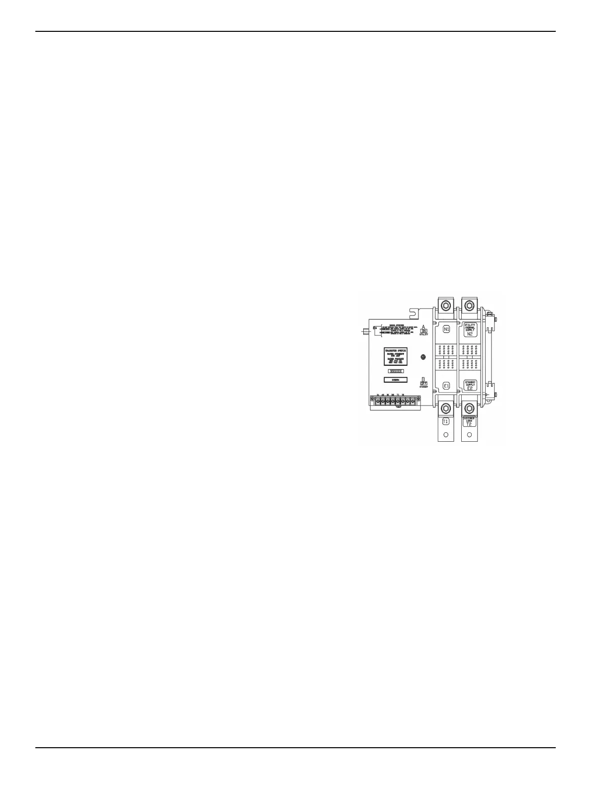
Transfer Mechanism
The transfer mechanism houses the main current-
carrying contacts, along with other mechanical and
electrical components required for operating the switch
(Figure 2-1). Main contacts are actuated by a single
solenoid, are electrically operated, and mechanically
held. Power for that coils operation is taken from the side
to which the load is being transferred. Transfer to any
power source cannot occur unless that power source is
available to the switch.
Load (or “T”) contacts are bolted to an insulated plastic
pole piece and are stationary. The normal (utility) and
standby (emergency) contacts are movable. The
contacts are actuated by means of a closing coil and
mechanical linkage. The pole assemblies which retain
the stationary movable main contacts are assembled
together and retained by through-bolts. Either 2, 3, or 4-
pole assemblies may be used to form a 2, 3, or 4-pole
mechanism.
Figure 2-1. The Transfer Mechanism
 Loading...