Installation
14 Automatic Transfer Switch Owner’s Manual
Installing PWRview Antenna
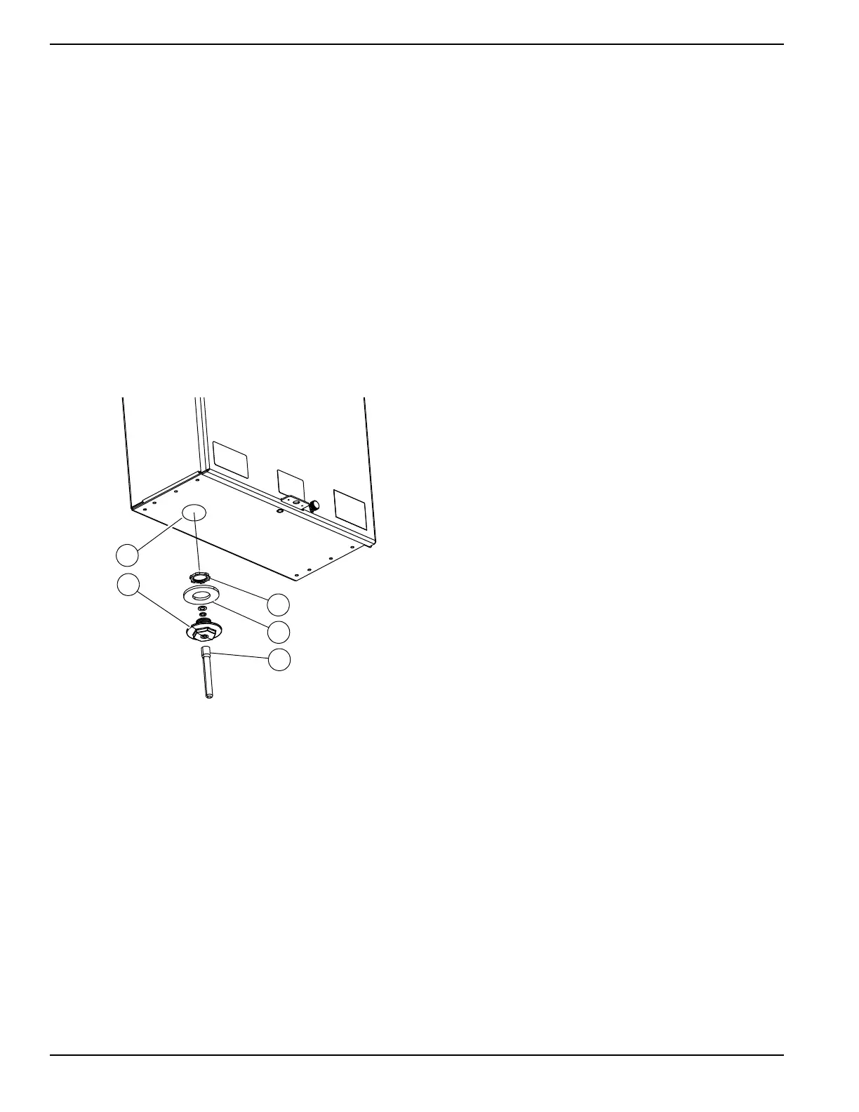
1.
See
Figure 3-6
.
Measure and create a 1/2 inch
knockout location (A) for antenna, preferably on
the bottom of the enclosure at least 6 inches from
any metal conduit. Avoid top mounting the antenna
for outdoor applications to minimize the chance of
water ingress.
2. Remove PWRview components from the bag
provided inside the switch.
3. Press antenna carrier (B) with sealing washer (C)
into the knockout hole and install the EMT nut (D).
Tighten firmly to ensure a good seal.
4. Insert antenna cable from PWRview monitor into
the antenna carrier.
5. Screw the included weatherproof antenna (E) onto
the antenna cable until it is snug against the
antenna carrier.
Figure 3-6. Install PWRview Antenna
Connecting PWRview CTs
1. Clamp one of the included CTs to the subpanel
supply line T1. "SOURCE THIS SIDE" marking
must face transfer switch contactor (away from
customer load).
2. Insert the CT connector into the CT1 port on the
PWRview device.
3. Clamp the second included CT around the
subpanel supply line T2. "SOURCE THIS SIDE"
marking must face transfer switch contactor (away
from customer load).
4. Insert the CT connector into the CT2 port on the
PWRview device.

 Loading...