Operation
Automatic Transfer Switch Owner’s Manual 13
Section 4: Operation
Functional Tests and Adjustments
Following transfer switch installation and interconnection,
inspect the entire installation carefully. A competent,
qualified electrician should inspect it. The installation
should comply strictly with all applicable codes,
standards, and regulations. When absolutely certain the
installation is proper and correct, complete a functional
test of the system.
IMPORTANT: Before proceeding with functional tests,
read and make sure all instructions and information in
this section is understood. Also read the information and
instructions of labels and decals affixed to the switch.
Note any options or accessories that might be installed
and review their operation.
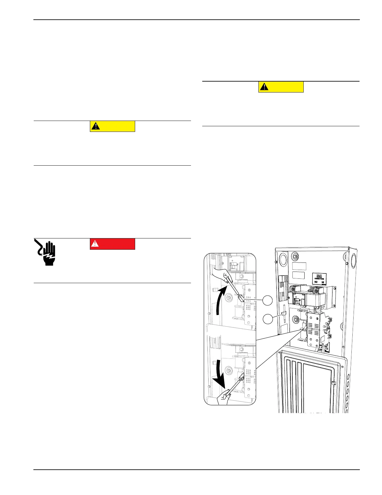
Manual Operation
See Figure 4-1. A manual handle is shipped with the
transfer switch and is stored in a bracket (B) within the
cabinet. Manual operation must be checked BEFORE the
transfer switch is operated electrically. To check manual
operation, proceed as follows.
IMPORTANT NOTE: Never manually operate the
transfer switch mechanism while it is energized with
utility or generator power.
1. Confirm the generator is OFF.
2. Turn OFF both UTILITY (service disconnect circuit
breaker) and EMERGENCY (generator main line
circuit breaker) power supplies to the transfer
switch.
3. Note position of transfer mechanism main contacts
by observing the movable contact carrier arm. This
can be viewed through the long narrow slot in the
inside cover of the ATS. The top of the movable
contact carrier arm is yellow to be easily identified.
• Manual operation handle in the UP position—LOAD
terminals (T1, T2) are connected to UTILITY
terminals (N1, N2).
• Manual operation handle in the DOWN position—
LOAD terminals (T1, T2) are connected to
EMERGENCY terminals (E1, E2).
Close to Utility Source Side
See Figure 4-1. Before proceeding, verify the position of
the switch by observing the position of manual operation
handle. If the handle is UP, the contacts are closed in the
NORMAL (UTILITY) position, no further action is
required. If the handle is DOWN, proceed with Step 1.
1. With the handle inserted into the movable contact
carrier arm (A), move handle UP. Be sure to hold
on to the handle as it will move quickly after the
center of travel.
2. Remove manual operating handle from movable
contact carrier arm. Return handle to storage
bracket (B).
Figure 4-1. Manual Operation
(000121)
CAUTION
Equipment damage. Perform functional tests in the
exact order they are presented in the manual.
Failure to do so could result in equipment damage.
(000132)
DANGER
Electrocution. Do not manually transfer under load.
Disconnect transfer switch from all power sources
prior to manual transfer. Failure to do so will result
in death or serious injury, and equipment damage.
(000122)
CAUTION
Equipment damage. Do not use excessive force
while manually operating the transfer switch.
Doing so could result in equipment damage.