Installation
Automatic Transfer Switch Owner’s Manual 11
Connecting Start Circuit Wires
Control system interconnections consist of N1, N2, and
T1, and leads 23, 0, and 194 (see Figure 3-3). The
generator control wiring is a Class 1 signaling circuit.
Reference instruction manual of specific engine
generator for wiring connection details. Screw heads are
straight bladed and cross-bladed, and should be
tightened to 3.5 in-lb (0.4 Nm).
Recommended wire gauge sizes depend on wire length
as specified in the following chart: Consult factory if you
are operating more than one transfer switch and SACM.
Exception: Conductors of AC and DC circuits, rated
1000 volts nominal, or less, shall be permitted to occupy
the same equipment, cable, or conduit. All conductors
shall have an insulation rating equal to at least the
maximum circuit voltage applied to any conductor within
the equipment, cable, or conduit.
Connecting SACM
See Figure 3-3. The SACM can control an air conditioner
(24 VAC) directly.
Control of Air Conditioner Load
1. Route the thermostat cable (from the furnace/
thermostat to the outdoor air conditioner unit) to the
transfer switch.
2. Connect the wire to the terminal strip terminals
(A/C 1) on the SACM as shown in Figure 3-3.
These are normally closed contacts which open
upon load shed conditions. Route thermostat wire
away from high voltage wires.
3. If required, connect additional air conditioners to
the terminal strip terminals (A/C 2-4).
NOTE: These instructions are for a typical air conditioner
installation. Control of certain heat pumps and 2-stage air
conditioners may require special connections or the use
of SMMs to control the loads.
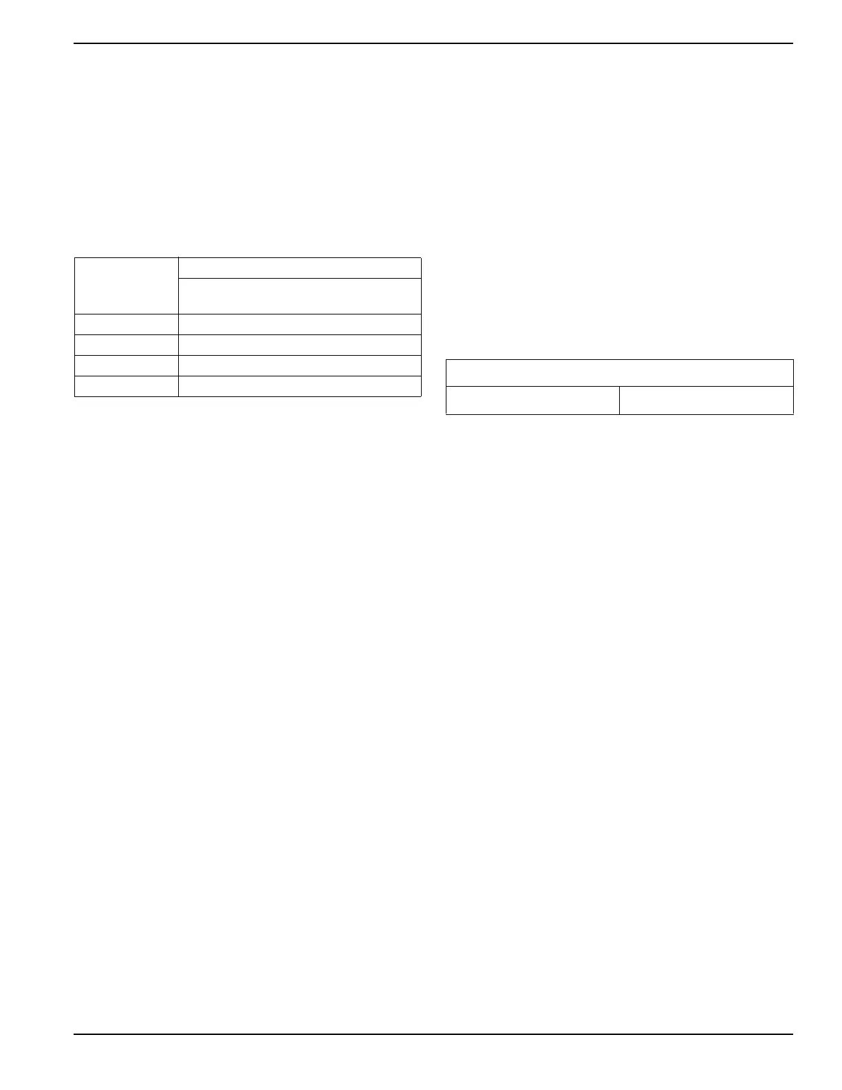
Recommended
Wire Size
Maximum Wire Length
( O n e t r a n s f e r s w i t c h
and load shed module)
No. 18 AWG 1–115 ft (0.3–35 m)
No. 16 AWG 116–185 ft (36–56 m)
No. 14 AWG 186–295 ft (57–89 m)
No. 12 AWG 296–460 ft (90–140 m)
Contact Ratings
A/C 1-4 24 VAC, 1.0 Amp Max