Section 10 - Electrical/Electronic Diagrams
The diagrams shown on the following pages illustrate the layout of, and the
connections between, the electrical and electronic components within Genesis
machines.
N.B. Instant, Freshbrew and Espresso machines are equipped with very similar
wiring arrangements. The following diagrams are common to all machines except
where stated.
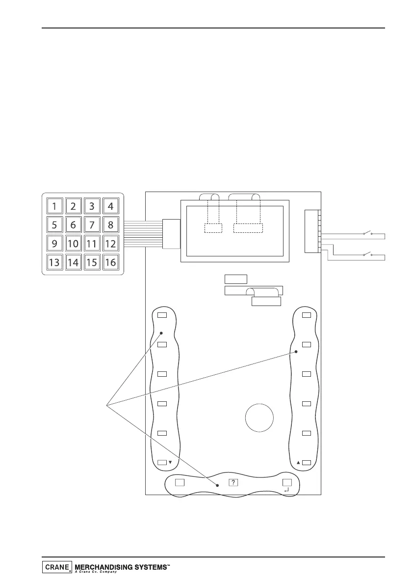
10.1 Console Board/Service Keypad
J5
8
5
6
7
3
4
1
2
BLACK/WHITE
PURPLE/GREEN
JUG KEY
SWITCH
BLACK/WHITE
WHITE/GREY
FREE VEND
SWITCH
LCD
SERVICE KEYPAD
J2J3
J4
RIBBON
CABLE
RIBBON
CABLE
CONSOLE BOARD
DRINKS SELECTION
AND PROGRAMMING
BUTTONS
PIEZO
SOUND DEVICE
MAIN CONTROLLER
BOARD LINK
RIBBON CABLE
XSTART
J6
NOT USED
J1
1
2
3
4
5
6
7
8
9
0
N.B. The Jug Switch and Free Vend Switch will only work with software versions
1.03 and above.
Technical Manual
95
 Loading...