1
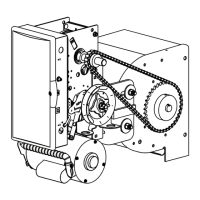
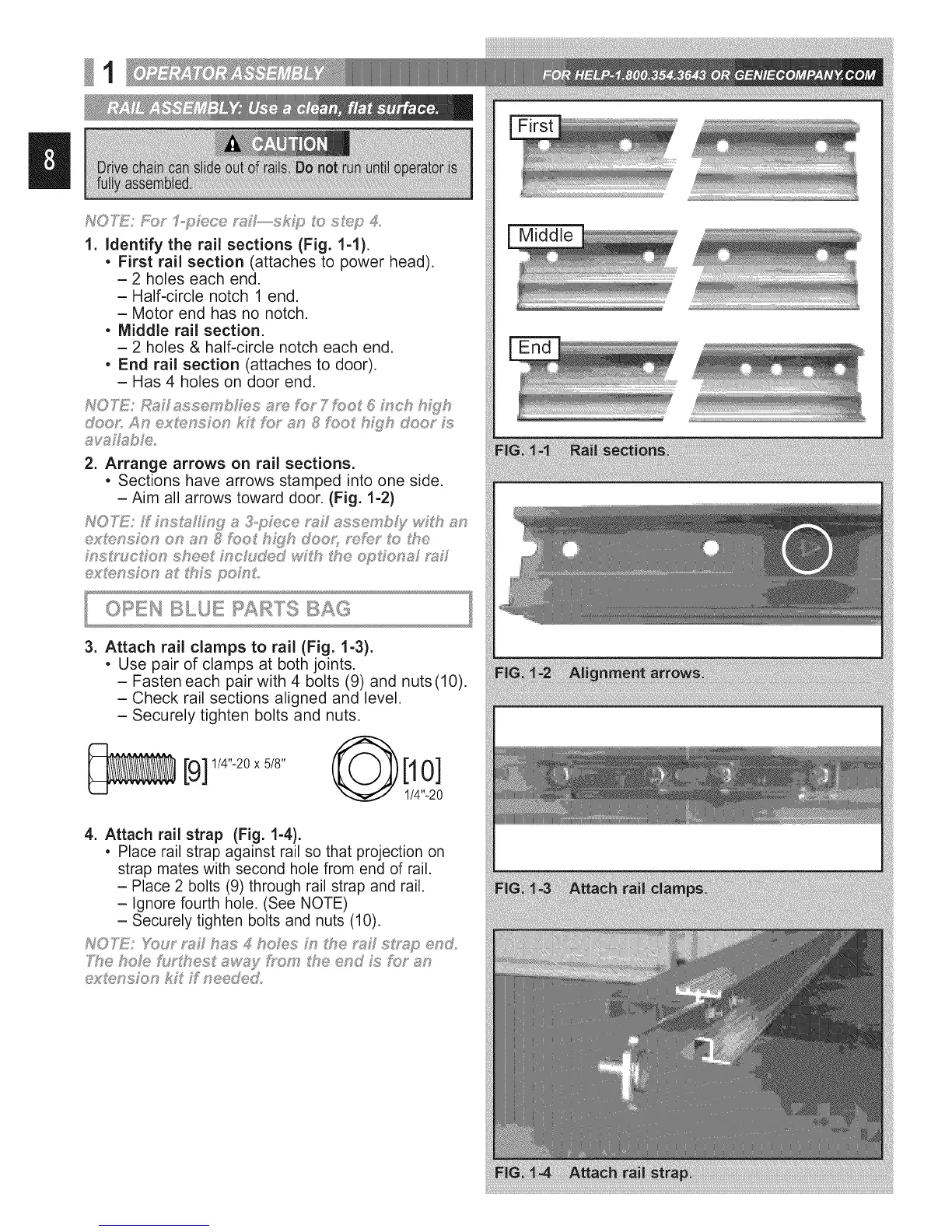
1. Identify the rai! sections (Fig. 1-1).
• First rail section (attaches to power head).
- 2 holes each end.
- Half-circle notch 1 end.
- Motor end has no notch.
• Middle rail section.
- 2 holes & half-circle notch each end.
• End rail section (attaches to door).
- Has 4 holes on door end.
2. Arrange arrows on rail sections.
• Sections have arrows stamped into one side.
- Aim all arrows toward door. (Fig. 1-2)
ex_ensFon on an _ foot h_yh doox_ _f_;_ t_f:_the
Middle
3. Attach rail clamps to rail (Fig. 1-3).
• Use pair of clamps at both joints.
- Fasten each pair with 4 bolts (9) and nuts(10).
- Check rail sections aligned and level.
- Securely tighten bolts and nuts.
[9] 114''-20x 518" @[10]
1/4"-20
4. Attach rail strap (Fig. 1-4).
• Place rail strap against rail so that projection on
strap mates with second hole from end of rail.
- Place 2 bolts (9) through rail strap and rail.
- Ignore fourth hole. (See NOTE)
- Securely tighten bolts and nuts (10).
cxUf:,nsFon kF Ffneede&
 Loading...