Do you have a question about the Genie GCL-MJ&MH and is the answer not in the manual?
Details safety terminology and critical instructions for safe operation.
Covers pre-installation, installation steps, and operator setup procedures.
Details operator features, troubleshooting, service, and maintenance information.
Key safety guidelines and precautions to follow before operating the door.
List of items to consider before selecting an operator for a specific job site.
Details requirements for fail-safe external reversing devices for safe operation.
Lists UL approved entrapment devices for compliance with UL325 requirements.
Chart detailing allowable door widths and specifications for rolling steel doors.
Chart detailing specifications for various types of sectional doors.
Crucial warnings and instructions to reduce the risk of severe injury or death during installation.
Instructions for assembling the operator for right-hand or left-hand mounting on rolling steel doors.
Details attaching the operator assembly and door sprocket for front of hood mounting.
Instructions for wall mounting the GCL-MJ&MH™ Rolling Steel unit using an optional kit.
Steps for mounting the operator for sectional doors using a chain couple system.
Guidance on ensuring proper chain tension for smooth operator function.
Detailed steps for attaching sprockets and chains for counterbalance door shafts.
Instructions for installing an optional chain spreader bracket for improved chain alignment.
Procedure for adjusting the operator's friction style clutch for proper protection.
Steps to adjust the brake mechanism for optimal spring tension and movement.
Guide for routing the hand chain, connecting ends, and mounting the chain keeper.
Instructions for connecting the operator to the main power supply, emphasizing safety.
Guide for connecting low voltage control circuits like wall controls and radio receivers.
Diagram showing external wiring connections for control signals and accessories.
Wiring instructions for 1, multiple 3-button, and single button accessory wall controls.
Warning about the placement and safety precautions for wall controls.
Details on installing optional interlock switches for door locks or pass-through doors.
Instructions for connecting radio controls and photocell systems for safety.
Steps for installing sensing edge switches, including wiring and connection methods.
Key safety warnings for operators, including testing, manual release, and door balance.
Overview of the control panel features, including LCD display, keys, and operating modes.
Critical safety warning regarding contact with internal control panel components.
Procedure to set the operator's open and close modes to constant contact for safe operation.
Instructions for setting the full open and closed limits for the door operator.
Procedure to adjust the limit overrun for proper door seal at the down limit.
Instructions for enabling and configuring monitored reversing devices like Safe-T-Beams.
Explanation and procedure for resetting the maximum run timers for operator protection.
Procedure for programming a mid-stop point for the operator during opening cycles.
Instructions for changing open and close modes to momentary contact if safety devices are installed.
How to view the built-in cycle counter that tracks operator usage.
Procedure to display the current firmware version number of the operator's micro-controller.
How to set the operator type (Jackshaft or Trolley) for correct configuration.
Explanation of how the operator's LCD display indicates status and error codes.
Information on the error code memory and how codes are displayed and stored.
How to view the operator's error code memory and understand its content.
Explanation of run code memory storing events for troubleshooting aid.
Procedure to view the run code memory and interpret the stored codes.
Example demonstrating how to use run and error codes to diagnose operator issues.
Explanation of diagnostic LED indicators on the circuit board for problem signaling.
Chart to diagnose issues with monitored photocells based on LED status.
Schedule of recommended service and maintenance items for the operator.
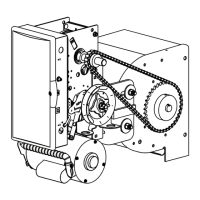
Illustrated parts list and breakdown for the basic hoist operator components.
Illustrated parts list and breakdown for the basic jackshaft operator components.
Detailed parts list and diagrams for basic shaft assembly components.
Detailed parts list and diagrams for basic shaft assembly components.
Illustrated parts list and breakdown for the electric box and its components.
Mapping of input terminals to functions and connection types for wiring.
Details on connections for radio, expansion port, transformer, brake, motor, and sensors.
List of condition codes displayed during operator run modes and their meanings.
List of error codes displayed by the operator and their corresponding condition descriptions.
Continuation of error codes, detailing specific board failures and operational faults.
Details warranty coverage, exclusions, and responsibilities for the commercial operator.
| Type | Chain Drive |
|---|---|
| Max Door Height | 7 ft |
| Horsepower | 1/2 HP |
| Voltage | 120V |
| Drive System | Chain drive |
| Remote Control | Included |
| Speed | 7 inches per second |
| Remote Controls | 2 included |