4.2
www.geniecompany.com 06-12
Drawbar Assembly (continued)
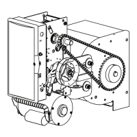
1) Attach Rails to Power Unit using four (4) 7/16”-14 x 1” bolts,
7/16”-14 keps nuts and 7/16” lock washers (provided). Fig. 2.
2) Attach the chain guide assemblies to the drawbar rails using
Track Bolts and locknuts (provided). Fig. 3.
Figure 3
CHAIN GUIDE BRACKET
TRACK BOLTS/
LOCKNUTS
PLASTIC CHAIN GUIDE
NOTE: Space chain guides evenly between operator and header. Add a chain
guide for every 4 feet of door height per chart.
NOTE: Chain Guide mounting holes have been pre-drilled at standard loca-
tions along the track. If different locations are needed, hole size should be
1/4" dia. Be sure to de-burr the holes.
UNDER 12’
12’ to 16’ 16’ to 20’ 20’ to 24’
2 3 4 5
CAUTION
Verify that screws are properly seated in track. Failure to seat screws can
cause carriage to bind in door track.
Figure 2
7/16"
BOLTS
Standard Duty Operator
GCL-T
 Loading...