Do you have a question about the Genie GS-2669 RT and is the answer not in the manual?
Identifies the serial number range for the models covered.
Key safety and operational instructions for maintenance.
Details machine classification and design life as per standards.
Notes on accuracy, product improvement, and change policy.
Information on how to contact Genie for support and inquiries.
Guidelines for individual safety when operating or maintaining the machine.
Guidelines for maintaining a safe and hazard-free work area.
Procedures for removing and servicing platform-related parts.
Procedures for disassembling and servicing the scissor lift mechanism.
Provides detailed specifications for fluid capacities, tires, and weight.
Details drive speed, braking distance, gradeability, and function speeds.
Specifications for hydraulic oil type, cleanliness, and optional fluids.
Technical specifications for the Kubota D1105 engine.
Torque values for Seal-Lok™ and JIC 37° fittings and SAE O-ring boss ports.
Key instructions and safety precautions before performing maintenance.
Explains symbols used to convey procedural information and warnings.
Details the types and frequencies of maintenance inspections required.
Information on the maintenance inspection report and record-keeping requirements.
Steps and legend for completing the pre-delivery inspection form.
Procedure to check operator and safety manuals and decals for legibility and completeness.
Visual inspection performed by the operator before each work shift.
Tests to ensure all machine functions are operating correctly.
Routine engine checks and maintenance procedures.
Procedure to verify the proper function of the oscillate system for stability.
Procedure to inspect and clean the engine air filter element for performance.
One-time service sequence performed after the first 30 days or 40 hours of usage.
Engine maintenance including oil and filter change at 50 hours.
Procedure for replacing the oil in the drive hubs after 150 hours.
Engine maintenance including oil/filter change, hose inspection, and air intake hose check.
Procedure to drain water and sediment from the fuel filter/water separator.
Procedure to recharge the battery for Kubota diesel engines.
Procedure to inspect battery condition, fluid levels, and specific gravity.
Procedure to inspect wiring for damage, corrosion, or loose connections.
Procedure to check tire condition, wheel damage, and lug bolt torque.
Procedure to verify the proper operation of the key switch for control selection.
Procedure to test the function of the emergency stop buttons on both controls.
Procedure to test the drive brake function for smooth, responsive operation.
Procedure to measure drive speed in the stowed position for performance verification.
Procedure to measure drive speed in the raised position for performance verification.
Procedure to test hydraulic oil for contamination levels for machine performance.
Procedure to check and maintain the oil level in the drive hubs for proper operation.
Procedure to calibrate the platform overload system for safe operation.
Procedure to check the descent delay function of the down limit switch.
Procedure to remove sediment from the fuel tank for engine performance.
Procedure to replace the hydraulic tank breather cap to prevent contamination.
Maintenance for Kubota D1105 and Perkins 403D-11 diesel engines.
Engine maintenance including inspecting valve clearance for Kubota diesel.
Procedure to measure wear pads and slider blocks for wear.
Procedure to replace the hydraulic tank return filter for system performance.
Annual engine maintenance for Kubota models including air filter and carburetor.
Engine maintenance for Perkins models including fan belt and valve lash.
Engine maintenance for Kubota Gas/LPG models including spark plugs and coolant system.
Procedure for replacing the oil in the drive hubs at 1000 hours or annually.
Maintenance for Kubota diesel models including inspecting injectors.
Procedure to test or replace hydraulic oil at 2000 hours or two years.
Maintenance for Perkins models including alternator, breather, engine mounts, and starter.
Two-year maintenance for Kubota Gas/LPG models including hoses and filters.
Two-year maintenance for Kubota diesel models including hoses, coolant, and air intake.
Maintenance for Perkins models including fuel injectors, water pump, and coolant system.
Maintenance for Kubota diesel models including injection pump and timing.
Critical safety and procedural notes for performing repair procedures.
Essential preparation steps and safety checks before commencing repairs.
Procedure for removing the platform controls circuit board.
Step-by-step procedure for removing the platform from the machine.
Step-by-step procedure to disassemble the scissor assembly for the GS-2669 RT.
Step-by-step procedure to disassemble the scissor assembly for the GS-3369 RT.
Step-by-step procedure to disassemble the scissor assembly for the GS-4069 RT.
Procedure for replacing scissor arm wear pads and slider blocks.
Information and removal procedures for lift cylinders.
Information on timing adjustment, noting it is factory sealed.
Procedure to test glow plug resistance and voltage.
Procedure to adjust low and high idle engine RPM for Kubota D1105.
Procedures for removing and installing the flex plate.
Explanation of switch operation and procedure for replacement.
Information on timing adjustment, noting it's factory sealed.
Information on carburetor adjustment, noting it's factory sealed.
Details choke operation and mode limitations.
Procedure to adjust low and high idle engine RPM for Perkins engines.
Procedures to adjust function speeds to compensate for wear.
Procedure to check the ECM software revision level.
Procedure to adjust the stowed drive speed for optimal performance.
Procedure to adjust the stowed high torque drive speed.
Procedure to adjust the raised drive speed for optimal performance.
Procedure to adjust the lift speed for optimal platform movement.
Procedures for configuring machine settings via the ground controls.
Explains various machine options like Descent Delay, Motion Alarm, and Overload.
Information and calibration procedures for the level sensor on non-outrigger models.
Information and calibration procedures for the level sensor on outrigger models.
Procedure to test the hydraulic pump pressure output.
Procedure for removing the hydraulic pump assembly.
Procedure for priming the hydraulic pump after replacement or service.
Lists and describes components of the function manifold with torque values.
Procedure to adjust the system relief valve pressure on the function manifold.
Procedure to adjust the oscillate relief valve pressure.
Procedure to adjust platform up relief valve pressure for models with overload system.
Identifies components of the outrigger manifold.
Lists components of the traction manifold (View 1) with functions and torque.
Identifies components of the generator manifold with functions and torque.
Specifications for testing valve coil resistance at different temperatures.
Procedure to test coils using the ECM's built-in test system.
Procedure for removing the fuel tank.
Procedure for removing the hydraulic tank.
Procedures for removing the yoke and drive motor assembly.
Procedure for removing the drive motor from the yoke.
Procedure for removing the steer cylinder.
Procedure for removing the tie rod.
Procedure for removing the oscillate cylinder.
Procedure to test the routing of oscillate axle hoses.
Procedures for removing the drive motor/brake assembly.
Procedure for removing the drive hub.
Procedure for removing the outrigger cylinder, if equipped.
Procedure to calibrate the platform overload system for safe operation.
Procedure to test the maximum height limit switch for proper operation.
Safety and preparation guidelines before starting troubleshooting.
Critical safety and procedural notes for troubleshooting and repair.
Diagram illustrating the general process for diagnosing and repairing malfunctions using fault codes.
Explanation of the diagnostic readout display and fault codes.
Lists error IDs and names related to ECU and switch faults.
Describes the conditions under which specific faults occur.
Provides solutions or troubleshooting steps for identified faults.
Overview of the schematics section, categorizing into electrical and hydraulic.
Details the electrical system of the machine.
Details the hydraulic system of the machine.
Details the pin assignments for the Electronic Control Module connectors.
Defines abbreviations, wire colors, and hydraulic component symbols.
Defines common electrical symbols used in schematics.
Defines common hydraulic symbols used in schematics.
Identifies and defines the location and function of various limit switches.
Illustrates the circuit diagram for the control panels.
| Brand | Genie |
|---|---|
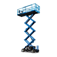
| Model | GS-2669 RT |
| Category | Boom Lifts |
| Language | English |