A
TYPICAL OPEN
BEAM CEILING
LAG
SCREWS
B
BOLTS/
NUTS
Attach hangers
(not
supplied)
LAG
SCREWS
(not
supplied)
Bolt 3/8" 16 x 7/8"
3/8"-16
Lock Nut
x 2
x 2
Use cross piece
(not supplied) for
attaching to
hidden joists.
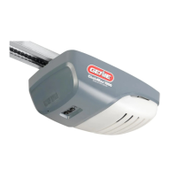
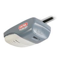
POWERHEAD
DOOR
WALLWALL
MEASURE HERE
MEASURE HERE
FINISHED CEILINGS
WITH HIDDEN JOISTS
directly to joists.
Support opener or have an
assistant hold it during this step
ACCESSORY
HOLES
Plug accessory
holes now.
NETWORK BBU
3-7/8" Clevis Pin, Long & Push Nut
x 1
WARNING
CAUTION
Header Bracket must be fastened to
garage framing. DO NOT fasten to
drywall, particle board, plaster, or
other such materials.
Door springs are under high tension. If spring or shaft is in the
way, measure above spring or shaft on the garage door
centerline and mark as location for header bracket. DO NOT
ATTEMPT TO MOVE, ADJUST, OR REMOVE DOOR SPRING!
CLEVIS PIN
and PUSH NUT
DOOR
CENTERLINE
HEADER
HIGHEST
POINT
of travel
PLUS**
TORSION SPRING
CEILING
WALL
TOP OF DOOR
HEADER
BRACKET
MAX. 6" FROM WALL
IN LOW OVERHEAD SITUATIONS,
HEADER BRACKET CAN BE MOUNTED
ON CEILING AS SHOWN
STEP 3 – Attaching Rail to Header
(part1)
USE ORANGE PARTS BAG
.gnivom si rood elihw gninepo fo raelc elpoep peeK •
• Do Not allow children to play with the door operator.
• Do Not .gnirps nekorb a sah taht eno ro smaj taht rood a etarepo
• Turn off power before removing operator cover.
raen ro dehcnip ton era seriw erus ekam ,revoc gnicalper nehW •
moving parts.
• Operator must be properly grounded.
• Do Not try to remove, repair or adjust springs or anything to
leets ,skcolb doow ,sa hcus ,denetsaf era strap gnirps rood hcihw
brackets, cables or other like items.
• Repairs and adjustments must be made by a trai
ned door system
.snoitcurtsni dna sloot reporp gnisu naicinhcet
DANGER
:
CAUTION
:
Overhead doors are large, heavy objects that move with the help of springs
under high tension and electric motors. Since moving objects, springs
under tension, and electric motors can cause injuries, your safety and the
fI .launam siht ni noitamrofni eht gnidaer uoy no dneped srehto fo ytefas
you have questions or do not understand the information presented, call
The Genie Company or your local Genie Factory Authorized Dealer.
In this section, and those that follow, the words Danger, Warning and
Caution are used to emphasize important safety information.
The word:
indicates an imminently hazardous situation
which, if not avoided, will result in death or serious injury.
indicates a potentially hazardous situation
which, if not avoided, could result in death or serious injury.
indicates a potentially hazardous situation
which, if not avoided, may result in injury or property damage.
The word NOTE is used to indicate important steps to be
followed or important considerations.
WARNING
:
WARNING–A MOVING DOOR
Could result in serious injury or death.
WARNING–AN ELECTRICAL SHOCK
Could result in serious injury or death.
WARNING–HIGH SPRING TENSION
Could result in serious injury or death.
TOOLS RECOMMENDED
P/N 37067501312
01-11
ASSEMBLY/INSTALLATIONINSTRUCTIONS
FOR
SCREW DRIVE MODEL GARAGE DOOR OPENERS
05-11
BLUE PARTS BAG ORANGE PARTS BAG
GREEN PARTS BAG
COTTER PIN (X 1)
TAPERED
FLANGE SCREW
1/4-14 x 3/4 (X 4)
(X 4)
LAG SCREW
5/16 X 1-3/4 (X 2)
LAG SCREW
5/16 X 1-3/4
(X 2)
HEADER
BRACKET (X 1)
WIRE CLIP (X 4)
CLEVIS PIN, LONG (X 1)
RELEASE
HANDLE
SELF-TAPPING SCREW,
1/4 X 3/4 (X 2)
INSULATED
STAPLE
1/4 X 3/4 (
˜
30)
BOLT,
5/16-18 X 3/4
(X 2)
LOCK NUT (SERRATED),
5/16-18 (X 2)
˜
(NOT INCLUDED
IN PRO UNITS)
L
3/8-16 (X 2)
CLEVIS PIN
3/8-15/16
(X 1)
DOOR
BRACKET
(X1)
SELF-DRILLING
SCREW,
1/4-20 X 3/4 (X 3)
LAG
COTTER PIN (X 1)
A E E
FLANGE SCREW
L
X 1)
1)(X )
STEP 1– Rail Assembly
STEP 2 – Attaching Rail to Powerhead
USE BLUE PARTS BAG
NOTE
STEP 3 – Attaching Rail to Header (part 2)
USE ORANGE PARTS BAG
PLUGS IN SMALL CLEAR BAG
Figure 1
1. If marked header bracket position
is above header, attach 2" x 6" board
across wall studs to create
mounting location.
2. Place bracket on your line and mark
hole locations. Drill 5/32" pilot holes.
3. Fasten bracket with lag
screws provided.
Figure 2
4. Carefully lean rail/opener assembly against garage door wall with
pulley assembly next to header bracket. Place cardboard, rag or any
soft material under powerhead to protect it. It may be necessary to
elevate the powerhead in order for the rail to clear the torsion spring.
5. Align pulley assembly and rail with side holes in
bracket and fasten with clevis pin and push nut.
STEP 4 – Mounting Powerhead
Continue supporting the opener.
(This step is easier with two people.)
1. Align opener with center of door. Measure from each side of door to where rail meets
powerhead. Measurements must be equal. Figure 1. Mark location.
2. Attach Mounting Straps in position.
3. While supporting opener, carefully open door. Raise opener to desired height, being
sure to allow clearance between rail and door as door passes through its highest point:
– This should be at least 2" on a one-piece door.
– Rail should be near level with fl oor on a sectional door.
4. Fasten opener to mounting straps using nuts and bolts indicated. Figure 2.
STEP 5 – Attaching Door Bracket
SECTIONAL DOOR (Lightweight)
Doors come both with & without braces where door bracket
attaches. Illustration a. and b. (without) and c. (with).
1. Regardless: the door bracket location is the same. On door centerline and higher than the top
set of door rollers.
• With a brace you may need to drill mounting holes through it. You may also be able to attach door
arm directly to the brace and eliminate the need for the door bracket.
2. Using door bracket as a template–mark the hole locations.
3. Drill 1/8" pilot holes and fasten with 1/4"-20 x 3/4" self-drilling screws provided.
SECTIONAL DOOR (Wooden)
1. Follow Lightweight instructions 1 and 2.
2. Drill 5/16" holes completely through door and fasten with 5/16" x 2" carriage bolts and nuts
(not furnished).
ONE-PIECE DOOR
1. Hold door bracket on door centerline, high as possible, on door face or top edge (preferred) and
mark hole locations.
2. For top edge (illustration d.):
• Drill 5/16" holes through door frame. Fasten with 5/16" x 2" bolts and nuts.
Face mount (illustration e.):
• Drill 5/16" holes through top door frame and fasten with 5/16" x 4-1/2" carriage bolts and nuts.
OR Fasten using 1-1/2" to 2" lag bolts. You must drill pilot holes to avoid splitting the frame.
USE ORANGE PARTS BAG
STEP 5b – Attaching Door Arms
USE BLUE & GREEN PARTS BAG
Figure 1
Figure 2
5/16"-18 x 1"
Bolt
5/16"-18
Lock Nut
x 2
x 2
x 1
x 2
Clevis Pin
3/8" x 15/16"
Cotter Pin
.073" DIA.
BLUE
BAG
GREEN
BA
G
BLUE
BAG
GREEN
BAG
USE BLUE PARTS BAG
DOOR
CENTERLINE
VERTICAL BRACE
OR
DOOR CENTERLINE
Doors made of masonite, lightweight wood, fiberglass, and sheet metal must be properly braced before mounting door
opener. Contact door manufacturer or distributor for any questions or concerns. The Genie® Company is not responsible for
any damage caused due to an improperly braced door.
CAUTION
a.
d.
b.
c.
e.
Rollers
ATTACH
NO LOWER
THAN TOP
ROLLERS
©2011 GMI HOLDINGS, DBA The Genie® Company
1/4-14 x 3/4"
Tapered Flange Screw
x 4
* Some units are equipped with amotion sensor.
Take special care to prevent damage.
This sensor works by detecting
body heat. Range of detection
may be reduced when temperature
in the garage is close to body
temperature. (DO NOT remove
foam cushion from underside
of opener.)
This opener includes parts and supplies needed for installation in MOST garages and on MOST garage doors. There are many variations of garages and
garage doors. A few additional parts and supplies may be needed for installation in YOUR garage and to YOUR garage door. While going over the checklist below,
used–does it extend far enough above the spring(s) to allow mounting of the Header Bracket. If not, or if you can’t tell–you will probably need a piece of 2" x 6"
need fasteners for mounting to the track itself or some other material? 4) Measure the height of your door. If it is taller than 7', you will need a Rail Extension Kit.
Is there an electrical outlet within approximately 3' of the point where the powerhead will be? If not you need to contact a licensed electrician.
Check condition of the door and all its associated hardware: Tracks, springs, hinges, rollers. Is anything loose or appear worn? If so, call a trained profes-
sional for an evaluation and repairs if needed. DO NOT ATTEMPT TO ADJUST SPRINGS OR THEIR ATTACHED PARTS!
Operate the door manually. Does it move freely and smoothly? Check the balance of the door by lifting it by hand approximately halfway open and let go. It
should stay put or move very slowly. If not, call a trained professional for repairs.
Remove all ropes and remove or disable all locks connected to the garage door. It is also recommended tha T-handles be removed. Closed loop lifting
handles with no protruding parts can remain.
1 READ AND FOLLOW ALL SAFETY, INSTALL ATION AND OPERATION INSTRUCTIONS. If you have any questions or do not understand an instruction, call The Genie®
Company or your local Genie® Factory Authorized Dealer.
2 Do Not install operator on an improperly balanced door. An improperly balanced door could cause severe injury. Repairs and adjustments to cables, spring
assembly, and other hardware must be made by a trained service person using proper tools and instructions.
3 Remove all ropes, and disable all locks connected to the door before installing operator.
4 Install door operator 7 feet or more above the floor. Mount the emergency release knob 6 feet above the floor.
5 Do Not connect the operator to the source of power until instructed to do so.
6 Locate the control button: A) Within sight of door. B) At a minimum height of 5 feet, so small children cannot reach it. C) Away from all moving parts of the door.
7 Install the entrapment WARNING label next to the wall button or console. Install the emergency release tag on, or next to, the emergency release Handle.
8 The operator must reverse when the door contacts
a 1-1/2 inch high object on the floor at the center of the doorway. This is about the size of a 2” x 4” board laid flat.
!
TO REDUCE THE RISK OF SEVERE INJURY OR DEATH:
WARNING
:
STEP 1
STEP 2
STEP 3
STEP 4
STEP 6
STEP 5
PUSH NUT
(X 1)
(X 2)
3
BOLT
COUPLER
8-16 X 7// 8
(X 2)
SAFE-T-BEAM® SOURCE (X 1)
SAFE-T-BEAM® SENSOR (X 1)
LAG SCREW,
1/4 X 1-1/4 (X 4)
SMALL CLEAR BAG
RUBBER
PLUGS, (X 2)
SMALL CLEAR BAG
CLIP, (X 2)
COLLAR, (X 2)
YELLOW PRT BAG
SAFE-T-BEAM® SOURCE
F
C
B
B
A
A
RAIL CONNECTOR
RAIL CONNECTOR
CARRIAGE
F
F
Mounting Straps
(set aside, not used
until INSTALL STEP 3)
G
Slide shuttle into door end of rail (NOTE DIRECTION). Rail fits into grooves
along sides of shuttle. When shuttle moves over the carriage, it will lock
into place.
F
F
F
B
C
A
B
DETAIL 1
DETAIL 2
A
D
E F
B
C
G
Opener End Rail Section, Middle Rail Section, Door End Rail Section
Screw Clips, Screw Collars, and Rail Connectors Mounting Straps
1. Sections of rail assembly slide together in order shown.
2. Slide screw connection end of opener end section into
rail connector
until it locks into place.
4. Slide
6.
Slide
middle section into same rail connector until it locks.
Check closely to ensure you connect proper end of section. Short screw connection piece mates
with long connection piece.
5.
Connect the two screw sections. Screw sections can be rotated for alignment.
See DETAIL 2 below.
8. Connect the two screw sections. See DETAIL below.
second rail connector onto middle rail section until it locks.
7.
Complete rail assembly by sliding screw connection end of door end section
(has a blunt ended screw) into rail connector until it locks.
3. Attach Shuttle to Carriage in middle section. See DETAIL 1 below.
INSTALLING
CLIPS & COLLARS
Slide Collar over long Hook
Slide Collar over Joint
Snap Clip behind Collar
1
3
4
Mate Hooks
2
ENGAGED
DISENGAGED
TOWARD
GROOVES
ALONG
SHUTTLE
DIRECTION
D
E
DOOR
The COUPLER, used to connect the drive screw to the
motor shaft, has a small hole on one end and a larger
hole on the opposite end.
• The smaller hole fits over the motor shaft.
• The larger hole fits over the drive screw.
3.
Place rail mounting bracket on top of rail
with tongue of bracket inserted into slot in rail.
MAKE SURE RAIL IS CLOSED SIDE UP-
SCREW UNDERNEATH.
4. Align holes in bracket with those on
power head* and fasten with tappered
flange bolts supplied.
COUPLER
TONGUE
TONGUE
Top of
Rail
SLOT IN RAIL
* Use soft material to cushion
under side of opener in order
to protect powerhead.
MOTOR
SHAFT
DRIVE
SCREW
SMALL HOLE
LARGE HOLE
1. Place shaft coupler large hole over end
2.
Align drive screw/coupler (small hole) with motor
shaft and slide together.
of drive screw.
Figure 1
MOTION
SENSOR
PROTECTIVE CUSHION
x 3
1/4"-20 x 3/4"
S
elf Drilling Screw
LINE UP AND CONNECT DOOR ARMS AS SHOWN.
MAKE SURE CARRIAGE IS DISENGAGED, SO IT WILL
MOVE AS NEEDED TO ALIGN HOLES.
SECTIONAL DOOR
1.
Straight arm attaches to carriage using
clevis pin and cotter pin provided
2. Curved arm attaches to door bracket using
clevis pin and cotter pin provided.
ONE-PIECE DOOR
1.
Straight arm only is used and connects to
carriage and door bracket both with clevis
pins and cotter pins provided.
SECTIONAL DOOR
HEADER
BOLT/
NUT
ADDED MOUNTING MATERIAL
A
WALL
A=
MAKE THIS THE
SHORTEST OVERALL
COMBINED LENGTH
OF THE DOOR ARMS
ONE-PIECE DOOR
DOOR
DOOR
WALL
HEADER
DISENGAGED
EMERGENCY RELEASE LEVER
CLEVIS PIN
COTTER PIN
DISENGAGED
EMERGENCY RELEASE LEVER
FACE
SPRING
SPRING
30° max.
BASIC
OVERHAND
KNOTS
Do this with door fully closed.
1.
Tie knot in one end of red emergency release cord.
2.
Pass opposite end of cord up through red emergency
release handle and through hole in carriage release lever.
3.
Adjust height of handle to at least 6' above floor, and
1.
4.
Using the Emergency Release Cord, place the carriage
in the disengaged position (See STEP 1, DETAIL 1).
tie off cord. Cut off extra cord.
RED EMERGENCY
RELEASE HANDLE
IWC
ENTRAPMENT
WARNING LABEL
WARNING
:
Use of any other wall control can cause unexpected operation of the door and loss of the lighting feature. Locate wall console
within sight of the door and far enough from door to prevent contacting it while operating the console. Must be at least 5 feet
above floor to prevent small children from operating it.
STB
1
2
3
4
5 6
BWC
OR
TO POWERHEAD
Wall console #1 Wall console #2
Wall console #1 Wall console #2
TO WALL CONSOLE #1
W
B/W
W
B/
W
W
B/W
W
B/W
BOTH TO POWERHEAD
STB BWC IWC
NOT
USED
NOT
USED
NOT
USED
NOT
USED
FROM STBs
FROM WALL
CONSOLE
Wire connector
on Powerhead
Wire connector on
Powerhead
WALL
CONSOLE
TERMINAL
CONNECTIONS
A
B
STEP 6 – Safe-T-Beam®
1. Safe-T-Beam® does not have to be mounted
on garage door frame. Can be mounted
anywhere along garage door wall. Must
have clear line of sight between them
and top of lens must be between
5"- 6" above fl oor.
2. Hold mounting brackets against
desired surface , mark holes fasten with
lag screws or appropriate fasteners for
the material.
3. Route two (2) lengths of two (2) conductor wire
from powerhead, along top of rail, across header,
one to right, one to left and down to Safe-T-Beam®.
4. Fasten wire to rail with wire clips spaced evenly
along rail.
5. Fasten to header and wall with insulated staples
and cut off excess wire.
OPTIONAL DUAL WALL CONSOLE INSTALLATION
STEP 7 – Installing Wall Console
USE ORANGE PARTS BAG
Use only a Series III wall console when adding a second. The optional second Genie® Series III wall
console must be purchased separately.
1. Route wire from powerhead to desired location for
wall console. Some homes are pre-wired and they may not be color-coded. The wall console circuit
is not polarized, therefore, either wire may be connected to either terminal without a problem.
2. Secure wire with insulating staples and cut off excess wire.
3. Attach wires to wall console as shown. Insert opposite end of wire through Control Wire Tube on
powerhead illustrated above and attach as shown.
4. Mount wall console with #6 screws provided.
5.
next to wall console.
STEP 10 – Connect to Power
with power cord
FOR GROUNDED OUTLET CONNECTION
1. Plug in the power cord. Coil excess cord and tape or twist tie it to top of powerhead (DO NOT
PLACE ABOVE LIGHT BULBS).
STEP 8 – Professional Connect to Power
FOR PERMANENT WIRING BY ELECTRICIAN
IF USING THE STANDARD POWER CORD,
SKIP TO STEP 9.
1. Cut existing wires OUTSIDE CHASSIS
.
2. The wire connections must be made INSIDE
CHASSIS, and there must be at least 6" of new
power supply line wire INSIDE CHASSIS. (Conduit
illustrated is optional.) (Conduit, strain relief and
wire nuts are not provided.)
WARNING:
DO NOT alter plug in any way! If you have no grounded
electrical outlets.
outlets, have one installed by a licensed electrician.
Opener must be properly grounded to prevent personal
injury and equipment damage. NEVER USE AN EXTENSION
CORD! Check local building codes for any requirement
that you must have a permanent hard-wired connection.
If required, it must be installed by a licensed electrician.
NEVER REMOVE MOTOR COVER. All work inside cover
must be performed by a licensed electrician using
proper tools and instruction.
STEP 9 – Finishing
)
WIRING CONNECTIONS
6. At Safe-T-Beam® source and sensor, attach wires at terminal screws.
Either wire may be connected to either terminal (Circuit is non-polar).
7. At powerhead, twist striped wires together. Twist white wires
together. Attach to plug-in terminals 1 & 2 (again either terminal is
fi ne). Bundle any excess slack and tape to top of powerhead
NOT DIRECTLY ABOVE LIGHT(S).
CONNECTION AT STB
CIRCUIT IS
NON-POLAR.
YOU MAY
CONNECT
EITHER WIRE
TO EITHER
TERMINAL.
LOCATED INSIDE LIGHT LENS
x 4
1/4"x 1-1/4"
Lag Screw
Top of
Bracket
6" max.
5" min.
NO HEIGHT ADJUSTMENT
IS NEEDED FOR FLOOR
MOUNTED UNITS.
SOURCE (red LED)
SENSOR
Wall
Mount
Floor Mount
STB
1
2
3
4 5 6
BWC AWC
WARNING
:
Verify there is NO POWER to the opener prior to
beginning any wiring installations or changes.
INSULATED STAPLES
x 4
WIRE CLIPS
WIRE
When using insulated staples, make only snug
enough to hold wire in place. Staples too tight
can cause damage to wire and cause
Safe-T-Beam® System to malfunction.
CAUTION
:
Wire Clips
95
ft
Wire
Adhesive pad on bottom. Remove paper
from adhesive pad and stick clip to rail.
30
Insulated
Staples
ORANGE
BAG
GREEN
BAG
NO WIRE OR STAPLES
PROVIDED IN PRO UNITS
OPERATOR STB CONNECTION
TO MAKE CONNECTIONS
Press in on orange tab, insert wire
into hole and release tab.
Press here to open lens. Use caution opening.
2. Swing lens up into place. It may be necessary
to squeeze lens slightly to align tabs with slots
at top of motor cover.
1. Install light bulbs and insert hinges into slots in
motor cover.
1
2
MOTOR COVER
MOTOR COVER
DO NOT EXCEED MAX. WATTAGE
1. The opener is now ready to program
for operation.
3 Instructions for programming the opener
are in your “OPERATION AND
MAINTENANCE MANUAL.”
CAUTION:
2. DO NOT RUN OPENER
UNTIL Travel Limits have been set.
Each light bulb must be 100 W or less.*
* Model 2562 requires light bulbs
of no more than 60 Watts.
1
2
TAB
HINGE
LATCH
USE YELLOW PARTS BAG
SERRE-FILS
WIRE NUTS
WHITE - NEUTRAL
GREEN - GROUND
BLACK - HOT
GND WIRE
CONNECTOR
TOROID
TOROID
SERRE-FILS
WIRE NUTS
WHITE - NEUTRAL
GREEN - GROUND
BLACK - HOT
GND WIRE
CONNECTOR
EXISTING
WIRE
NO TOROID
TOROID
NOT
USED
NOT
USED
NOT
USED
NOT
USED
WALL CONSOLE
CONNECTIONS
AT POWERHEAD
Post Entrapment Warning Label
STB BWC IWC
NOT
USED
NOT
USED
FROM STBs
FROM WALL
CONSOLE #1
FROM WALL
CONSOLE #2
x 2
5/16" x 1-3/4" Lag Bolt
**Highest point of travel plus:
Sectional door = Highest point plus 2.5"
One-piece door = Highest point plus 6"
THE RAIL IS CONNECTED
WITH THE CLOSED SIDE
FACING UP. THE SCREW WILL
BE UNDERNEATH AND NOT
VISIBLE WHEN VIEWED
FROM ABOVE.
3. Ensure latch snaps into place.
Opener is equipped with grounded electrical plug for