SmartObserver User Manual
SmartObserver Data Logger
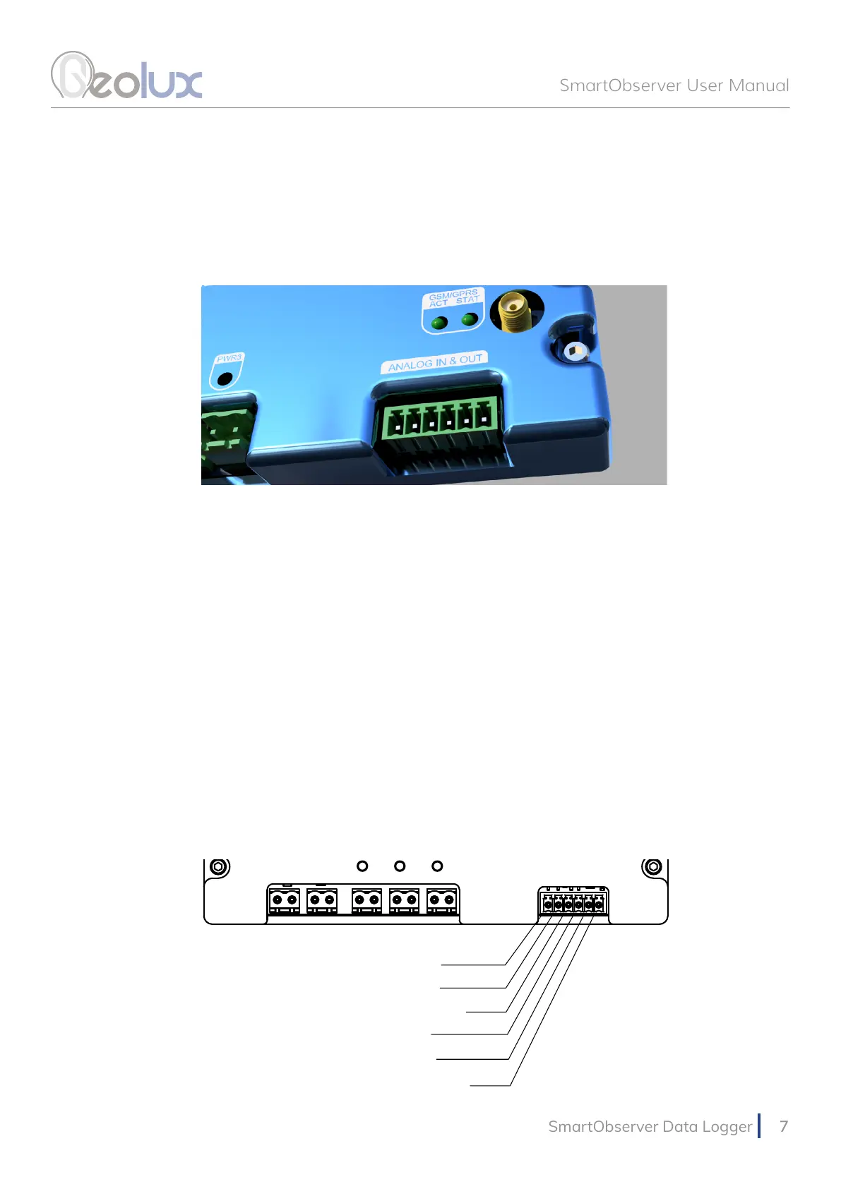
Picture 7. Analog Inputs and Outputs
4.5. Analog Voltage Inputs
The SmartObserver data logger contains two analog voltage inputs, ADC1 and ADC2, which can
measure analog signal with voltage ranging up to 30 volts. The pin-out is shown in Picture 8.
4.6. Analog 4 – 20 mA Output
The SmartObserver’s 4 – 20 mA interface is used to connect instruments compliant with industry-
standard 4 – 20 mA. The pin-out can be seen in Picture 8.
4.7. Analog Voltage Output
The SmartObserver data logger contains one analog output pin which can output analog signal
with voltage in the range of 0-5 V. This line is currently not used and is reserved for future use. The
pin-out is shown in Picture 8.
Picture 8. Analog Inputs and Outputs Pin-Out
Lines for interfacing analog instruments are located on the bottom part of the SmartObserver data
logger, as shown in Picture 7. From left to right, there are two analog voltage inputs, one 4-20 mA
interface and one analog output.
ADC-IN1
ADC-IN2
GND
4-20mA IN
DAC OUT
GND