SmartObserver User Manual
SmartObserver Data Logger
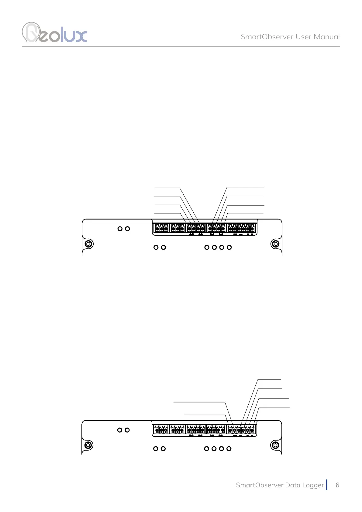
4.2. CAN
The SmartObserver data logger contains two CAN ports. The pin-out can be seen in Picture 5.
4.3. RS-485 (Modbus) Interface
Two RS-485 (Modbus) ports are available on the SmartObserver data logger. The pin-out is
shown in Picture 5.
Picture 6. SDI-12 and Digital GPIO Pin-Out
4.4. SDI-12 Interface
The SDI-12 interface is also located on the upper part of the SmartObserver data logger. The pin-
out is can be seen in Picture 6.
4.4. Digital GPIO Lines
The SmartObserver data logger contains two general-purpose digital outputs and two general-
purpose digital inputs. These lines are currently not used and are reserved for future use. The pin-
out is shown in Picture 6.
CAN1 H
CAN1 L
CAN2 H
CAN2 L
RS485-2 D-
RS485-2 D+
RS485-1 D-
RS485-1 D+
Picture 5. CAN and RS-485 Lines Pin-Out
GPOUT-2
GPOUT-1
GPIN-2
GPIN-1
SDI-12 DATA
SDI-12 PWR +5V