SmartObserver User Manual
SmartObserver Data Logger
4
Connecting Instruments to the
SmartObserver Data Logger
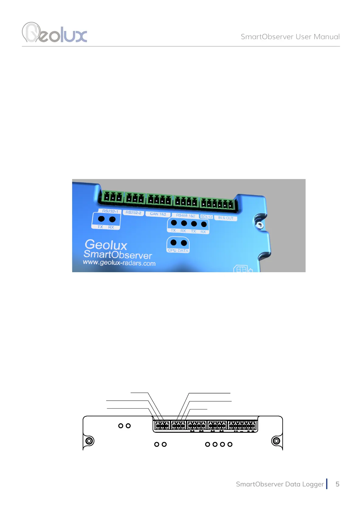
The SmartObserver data logger supports multiple communication interfaces for interfacing
instruments. Digital communication interfaces are located on the top part of the data logger as
show in Picture 3. From left to right, there are two RS-232 lines, two CAN bus ports, two RS-485
(Modbus) lines, one SDI-12 interface, two general-purpose digital inputs and two general-purpose
digital outputs.
4.1. RS-232 Interface
There are two RS-232 lines on the SmartObserver data logger. The RS232-1 line is used
to connect the data logger to the PC for data logger setup through the Geolux Instrument
Congurator application, as described in chapter 6 of this manual. The RS232-2 line can be used
to connect the Geolux HydroCam camera to the SmartObserver data logger. The HydroCam
camera can also be connected to the RS232-1 line when the SmartObserver data loggr is not
connected to the PC. When connecting the HydroCam camera, connect the green wire to the RXD
pin, the yellow wire to the TxD pin and the grey wire to the GND pin. The pin-out is displayed in
Picture 4.
Picture 3. Digital Communication Interfaces
Picture 4. RS-232 Lines Pin-Out
RS232-1 TXD
RS232-1 RXD
GND
GND
RS232-2 RXD
RS232-2 TXD