SmartObserver User Manual
SmartObserver Data Logger
3.3. Output Power
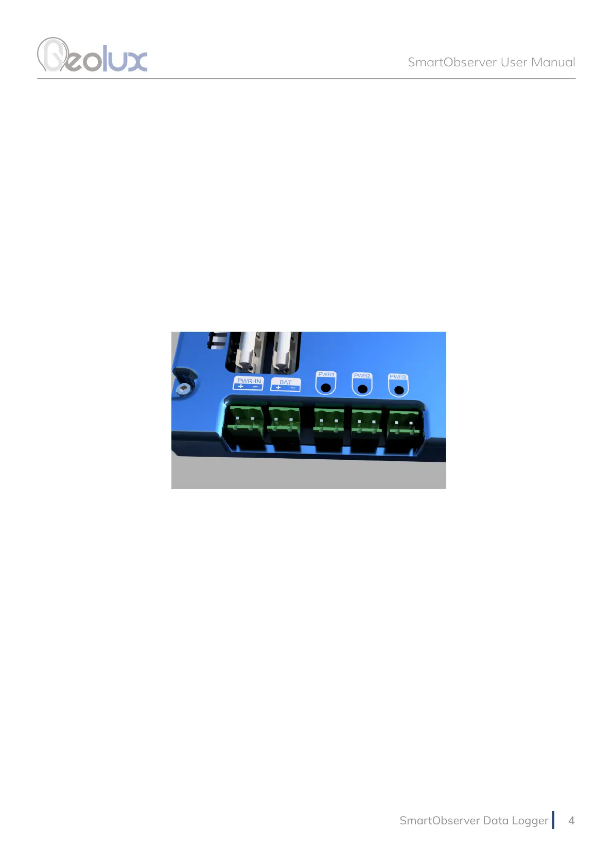
There are three output power lines, as show in Picture 2. They are labeled PWR1, PWR2 and
PWR3. These lines are used as a power supply to the instruments connected to the data logger.
The instruments at the monitoring site should be powered through the data logger, by connecting
them to these lines, because the data logger turns off the power supply on these three lines
between periodic measurements, in order to increase battery life.
Each of these three output lines outputs system voltage (it depends on the current battery and
PWR-IN voltages), and the maximum output current is 1 A. When connecting the instruments
to PWR1, PWR2 and PWR3 lines, consult the user manuals of the instruments to check the
maximum current drain of all instruments on a power line, to make sure that 1 A current is not
exceeded.
3.4. LED Indicators
The following LED indicators on the data logger provide useful diagnostics information:
• Internal power (+5V, +3V, +6V) LEDs indicate that the internal power supply for various
subsystems is active. Please note not all internal power systems will be active at all times while
the data logger is operating.
• RS232-1 TX and RX LEDs indicate activity on RS232-1 communication interface. The TX LED
will lit up every time the data logger sends some data over the RS232-1 interface, and the RX
LED will lit up when the data logger receives some data over the RS232-1 interface.
•
RS485 TX and RX LEDs indicate activity on both RS485-1 and RS485-2 interfaces. The TX
LEDs indicate that the data logger is sending some data over the interfaces, and the RX
LEDs indicate that data is being received by the data logger.
• CPU data LEDs – the left CPU LED should periodically blink every second, to indicate
that the internal CPU is operational. The right CPU LED is active when the data logger is
communicating with the instruments.
•
PWR1, PWR2 and PWR3 LEDs indicate when output power line 1, output power line 2
and output power line 3 are active.
• GSM/GPRS ACT & STAT LEDs indicate GPRS modem activity; blinking of ACT LED
indicates modem activity (communicating with the wireless network), and STAT LED
indicates data transfer status.
Picture 2. Input and Output Power Supply