Do you have a question about the GeoMax ZTS600 and is the answer not in the manual?
Congratulates user and introduces manual.
Information on where to find model and serial number.
Overview of the instrument, office software, and data transfer.
Lists all items included in the product packaging.
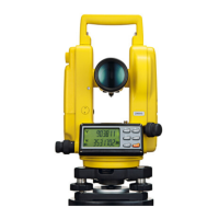
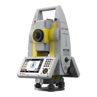
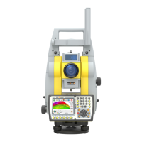
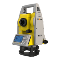
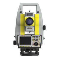
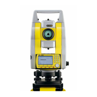
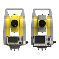
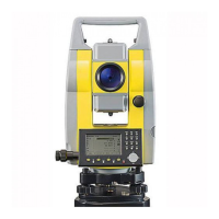
Details the physical parts and features of the instrument.
Explains the layout and function of the instrument's keypad.
Describes the meaning of various icons displayed on the instrument screen.
Explains the functionality of softkeys and their relation to function keys.
Details how to operate the instrument's basic functions.
Describes how to find measured or fixed points in memory storage.
Step-by-step guide for setting up the instrument for accurate measurements.
Instructions on battery charging, operation, and handling for continuous use.
Explains how data is stored internally and transferred to other devices.
Describes the main menu as the starting point for all instrument functions.
Details how to initiate the measurement process.
Provides best practices for accurate distance measurements.
Sets general instrument parameters like contrast and vertical angle reference.
Configures parameters for data transfer between instrument and computer.
Sets parameters for the Electronic Distance Measurement modes.
Allows defining a custom startup sequence for the instrument.
Displays instrument, system, and firmware details.
Procedures to correct line-of-sight and vertical index errors.
Calibrates the circular level on the instrument and tribrach.
Details how to inspect and check the laser plummet.
Provides an overview of the available functions accessible via the FNC key.
Calculates target point coordinates when direct setup is not possible.
Determines the instrument's height from measurements to target points.
Measures to hidden points using a special hidden point pole.
Calculates and displays differences between two measured points.
Activates or deactivates the tracking measurement mode.
Assigns codes to points for simplifying later processing.
Allows quick selection of predefined codes via the keypad.
Guides the user through selecting and starting an application.
Defines the job where data will be saved, enabling data organization.
References all measurements and computations to the set station coordinates.
Sets the orientation of the station manually or from known points.
Describes common fields found across firmware applications.
Measures an unlimited number of points for general surveying.
Places marks in the field at predetermined points.
Determines the instrument's position by measuring to known points.
Facilitates setting out or checking lines, including line & offset.
Allows defining a reference arc and performing tasks relative to it.
Computes distance, height difference, and azimuth between two points.
Computes areas of up to 50 points, 2D or 3D.
Computes points above a base prism without a prism at the target.
Defines a construction site and stakes out points relative to a line.
Performs coordinate geometry calculations like inverse and traverse.
Measures or sets out points relative to lines, curves, or spirals.
Overview of functions for entering, editing, checking, and deleting data.
Exports job data from the instrument via RS232 serial interface.
Describes the software package for data exchange and support.
Importance of checking and adjusting instrument accuracy over time.
Steps to prepare the instrument for calibration checks.
Procedures to correct line-of-sight and vertical index errors.
Calibrates the circular level on the instrument and tribrach.
Details how to inspect and check the laser plummet.
Provides instructions on maintaining and servicing the tripod.
Guidelines for safely transporting the equipment in various environments.
Guidelines for storing the instrument and batteries to preserve condition.
Procedures for cleaning and drying instrument components.
Enables users to anticipate and avoid operational hazards.
Specifies permitted uses and lists adverse usage scenarios.
Specifies environmental conditions and limitations for product use.
Outlines responsibilities of manufacturer, accessory makers, and user.
Warns about potential hazards from incorrect use or lack of instruction.
Classifies laser components and provides safety guidelines.
Safety regarding the laser used for distance measurements with reflectors.
Safety regarding the laser used for distance measurements without reflectors.
Safety information related to the laser plummet feature.
Discusses how the product interacts with electromagnetic fields.
Regulatory compliance statement for the US market.
Details accuracy and display resolution for angle measurements.
Provides ranges and conditions for reflector-based distance measurements.
Provides ranges and conditions for reflectorless distance measurements.
Specifies ranges and conditions for RL measurements to prisms.
Declares compliance with European Directives and relevant regulations.
Comprehensive instrument specifications including telescope and compensation.
Explains scale correction and automatic corrections applied by the instrument.
Details the mathematical formulas used for distance and height calculations.
Defines key axes of the instrument like line of sight and standing axis.
Deviation from perpendicular between tilting axis and line of sight.
Deviation in vertical circle reading when line of sight is horizontal.
| Angle accuracy | 2" |
|---|---|
| Operating temperature | -20°C to +50°C |
| Protection class | IP55 |
| Accuracy (Angle Measurement) | 2" |
| Telescope Magnification | 30x |
| IP Rating | IP55 |
| Distance measurement range with prism | 5, 000 m |
| Non-Prism Range | up to 1000m |
| Display | Dual color touch screen |
| Laser plummet accuracy | 1.5 mm at 1.5 m |
| Measuring Range (Distance without Reflector) | up to 1000m |
| Measuring Range (Distance with Reflector) | 5, 000 m |
| Weight | 5.1 kg |