offered by Busse-Yachtshop.com
••••••••••••••••••••••••••••••••••••••••••••••••••••••••••••••••••••••••••••••••••••••••••••••••••••••••••••••••••••••••••••••••••••••••••••••••••••••••••••••••••••••••••••••••••••••••••••••••••••••
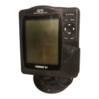
1918
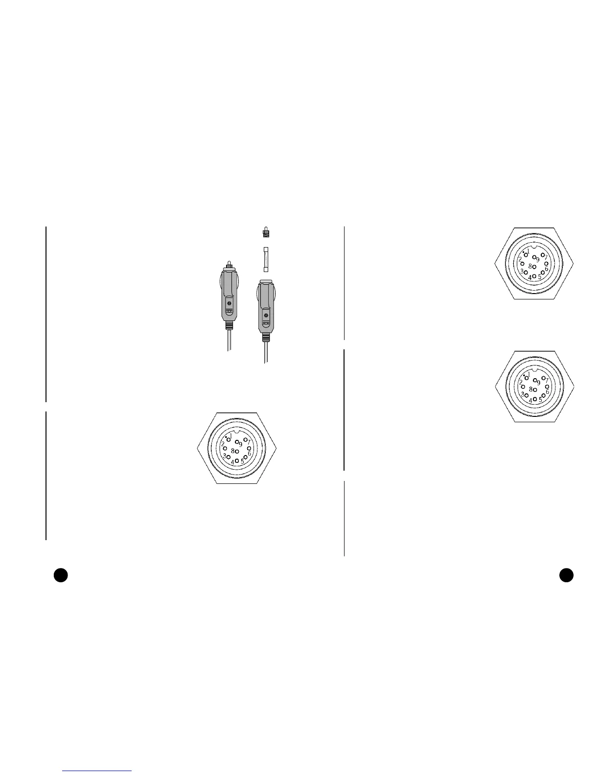
Connector and power supply / data cable
1. Power supply input
red wire Vin + (11-18VDC),
250mA pin 1
black wire Vin - pin 2
2. Ext. GPS data input
brown wire data in + pin 3
yellow wire data in - pin 4
3. Autopilot data output
violet wire data out + pin 5
white wire data out - pin 6
4. Depth sounder data input
blue wire data in + pin 7
green wire data in - pin 8
SHIELD pin 9
Connector and power supply / data cable
1. Power supply input
red wire Vin + (11-18VDC),
250mA pin 1
black wire Vin - pin 2
2. Ext. GPS/DGPS data input
brown wire data in + pin 3
yellow wire data in - pin 4
3. Autopilot data output
violet wire data out + pin 5
white wire data out - pin 6
4. Anemometer/depth sounder
data input
blue wire data in + pin 7
green wire data in - pin 8
SHIELD pin 9
CONNECTIONS
Power supply cable
The car lighter adapter has a little lamp
(LED) that goes on if the car is correctly pro-
viding power to the bracket.
If the lamp is off:
• verify that 12V voltage is available from
the lighter plug;
• open the adapter and check the fuse.
If the fuse is broken, replace it with a fuse
having the same electrical characteristics.
DO NOT USE ANY BYPASS CIRCUIT.
The fuse ensures that the special protec-
tion circuit inside the plotter works prop-
erly in case of accidental short-circuit, po-
larity inversion and overvoltage.
If you has to remove the lighter adapter,
internal connections are the following:
red (or white) +(+12V)
black - (ground)
Connector and data cable
1. Auxiliary output voltage (Vaux)
red wire Vaux +, 250mA pin 1*
black wire GND pin 2
2. Data input ext. GPS/DGPS
brown wire ext. GPS in + pin 3
yellow wire ext. GPS in - pin 4
3. Data output
violet wire Autopilot out + pin 5
white wire Autopilot out - pin 6
4. Data input depth sounder
blue wire DS in + pin 7
green wire DS in - pin 8
SHIELD pin 9
* Vaux voltage is the same as the plotter’s input voltage.
Connections
If sent by the autopilot, the following NMEA messages are transmitted to
external devices: GGA - RMC - ZDA
The GEONAV will add the following messages: APA - APB - XTE - RMB -
BWC - GLL - VTG
The data cable is supplied together with the GEONAV plotter.
WARNING: Once the installation is completed, always make sure that all wires are properly con-
nected since wrong connections may damage the unit.
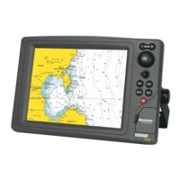
Plus
Elite
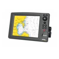
Elite
Cabin
Regatta
Elite
Cabin
Regatta
fuse
LED