Chapter 9 Auxiliary Device Connectors
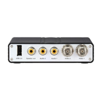
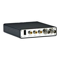
9.1 GV-VS04H and GV-VS14
The 16-pin terminal block, located on the rear panel, provides interfaces for four digital
inputs, four relay outputs, an RS-485 interface, a Wiegand interface, a GPS interface and
auxiliary power. The terminal block can be used to develop applications for motion
detection, event alerts via E-mail and FTP, center monitoring by Center V2 and VSM, PTZ
control, Wiegand-interface card reader and a variety of other functions.
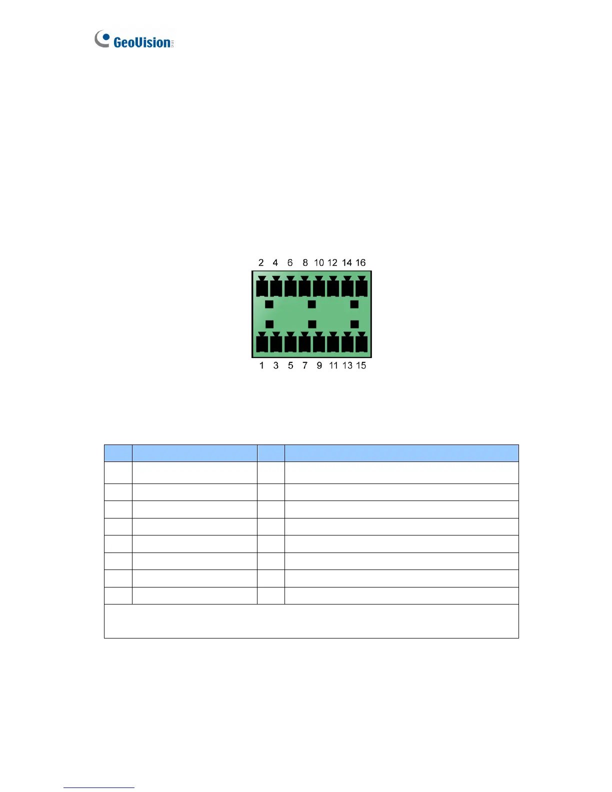
Figure 9-1
9.1.1 Pin Assignment
The table below lists the pin assignment for the terminal block.
Pin Function Pin Function
1 Relay Output 1 9 DC 5V Out for GV-Relay Module, or GPS Module
2 Digital Input 1 10 Ground, or GPS Ground
3 Relay Output 2 11 RS 485+
4 Digital Input 2 12 Wiegand D0, or GPS RX
5 Relay Output 3 13 RS 485-
6 Digital Input 3 14 Wiegand D1, or GPS TX
7 Relay Output 4 15 Ground
8 Digital Input 4 16 DC 12V Out for Wiegand Card Reader
Note: To connect the GPS module, use the Pin 9 for power supply, Pin 10 for ground, Pin
12 for GPS RX and Pin 14 for GPS TX.
136
 Loading...