32 LRR 1-52, LRR 1-53, URB 55 - Installation & Operating Manual - 850645-01
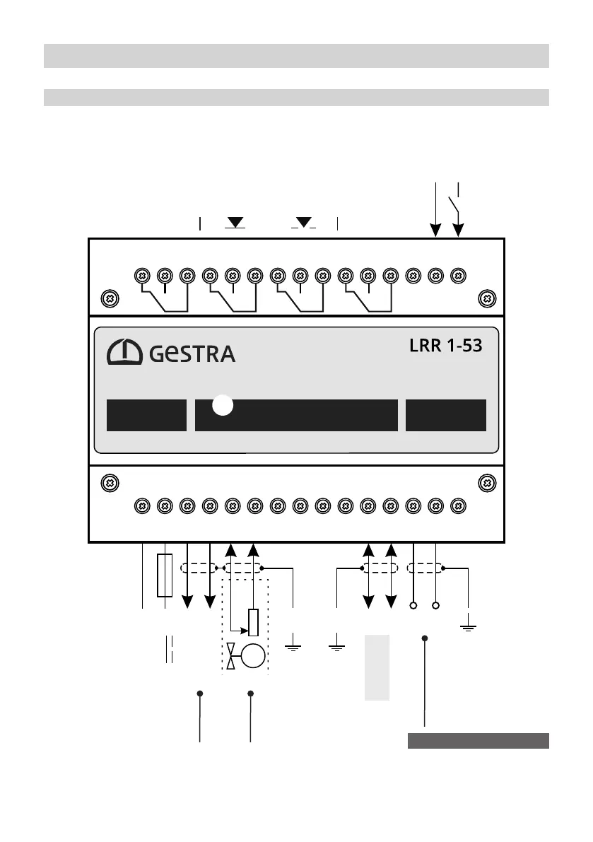
Wiring diagram - LRR 1-53 conductivity controller
Connecting an LRGT 1x-x conductivity transmitter (4 - 20 mA) with earthing point
MIN alarm
relay output
or
Actuates an
intermittent blowdown valve
MIN
Actuates a continuous
blowdown valve
CLOSED OPEN
MAX alarm
relay output
MAX
Supply voltage,
fuse provided by
customer M 0.5A
Actual value/manipulated
variable output
(switchable)
Display of valve position
(potentiometer 0 - 1000 W)
Data line
for URB 55
M
= shield
LRGT 1x-x
Conductivity transmitter
(4-20 mA) with earthing point.
Fig. 18
+
–
24 V DC
2716 17 18 19 20 21 22 23 24 25 26 28 29 30
123456789101112131415
24 V DC
+
–
M 0,5 A
+
–
0 - 1K
Ω
–
+
H L
S S
+
–
Standby input for an external command:
Control OFF / Valve CLOSED / Intermittent blowdown OFF
 Loading...


