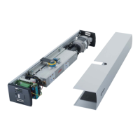
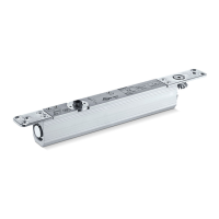
GEZE Perlan AUT-NT
10
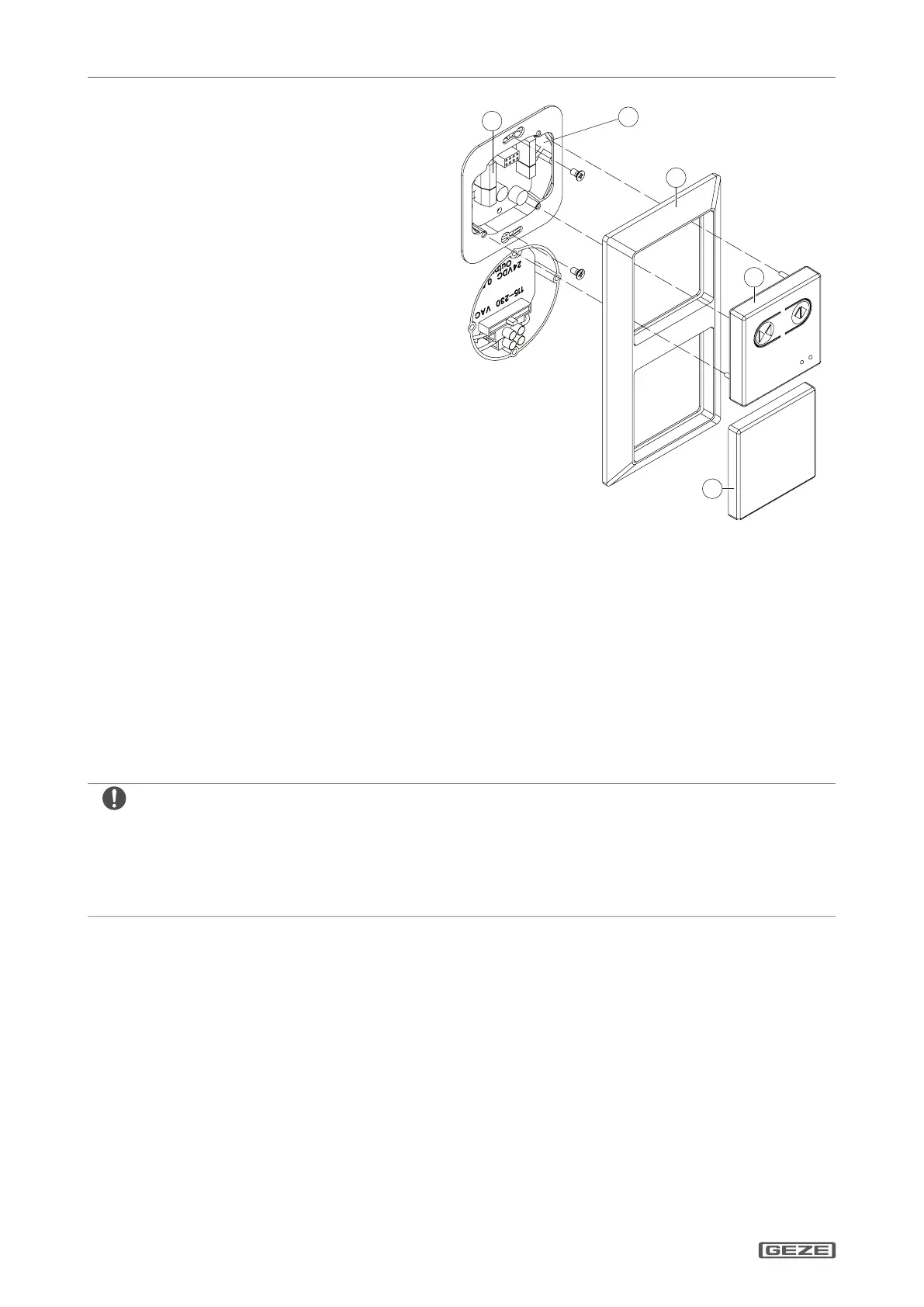
Contactors
X
Fasten the controller (2) in the ush-mounted
box (1) with screws.
X
Mount the 2-fold cover frame (4) for vertical
installation.
X
Mount the cover (6) onto the 2-fold cover frame
(4).
X
Put the switch (5) onto the controller (2).
4
5
6
1
2
Accessories programme switches GEZE:
à Frame 1-fold, Alpine white, ush-mounted, Mat. No. 115376
à Frame 2-fold, Alpine white, ush-mounted, Mat. No. 115377
à Frame 3-fold, Alpine white, ush-mounted, Mat. No. 115378
à Cover, AS500, Mat. No. 118480
à Surface-mounted box 1-fold, Alpine white, Mat. No. 120503
à Surface-mounted box 2-fold with AS500 cover, Alpine white, Mat. No. 128609
à Surface-mounted box 3-fold with AS500 cover, Alpine white, Mat. No. 133206
9 Contactors
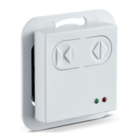
9.1 Radar movement detector GC 302 R
à An additional power pack 230V / 24V Perlan AUT-NT is required to supply external actuation elements.
X
Take the maximum permissible current draw into account when an additional power pack is used (500mA).
Wiring instructions:
X
Lay the conductors so that single-insulation power conductors do not cross single-insulation 24 V low voltage
conductors.
X
If necessary, insulate the power and low-voltage conductors additionally with shrink tubing.
à When the contactor is actuated, the contact is closed (0 V applied to the Input 21).
 Loading...