- 16 -
8S651MP-RZ Series Motherboard
English
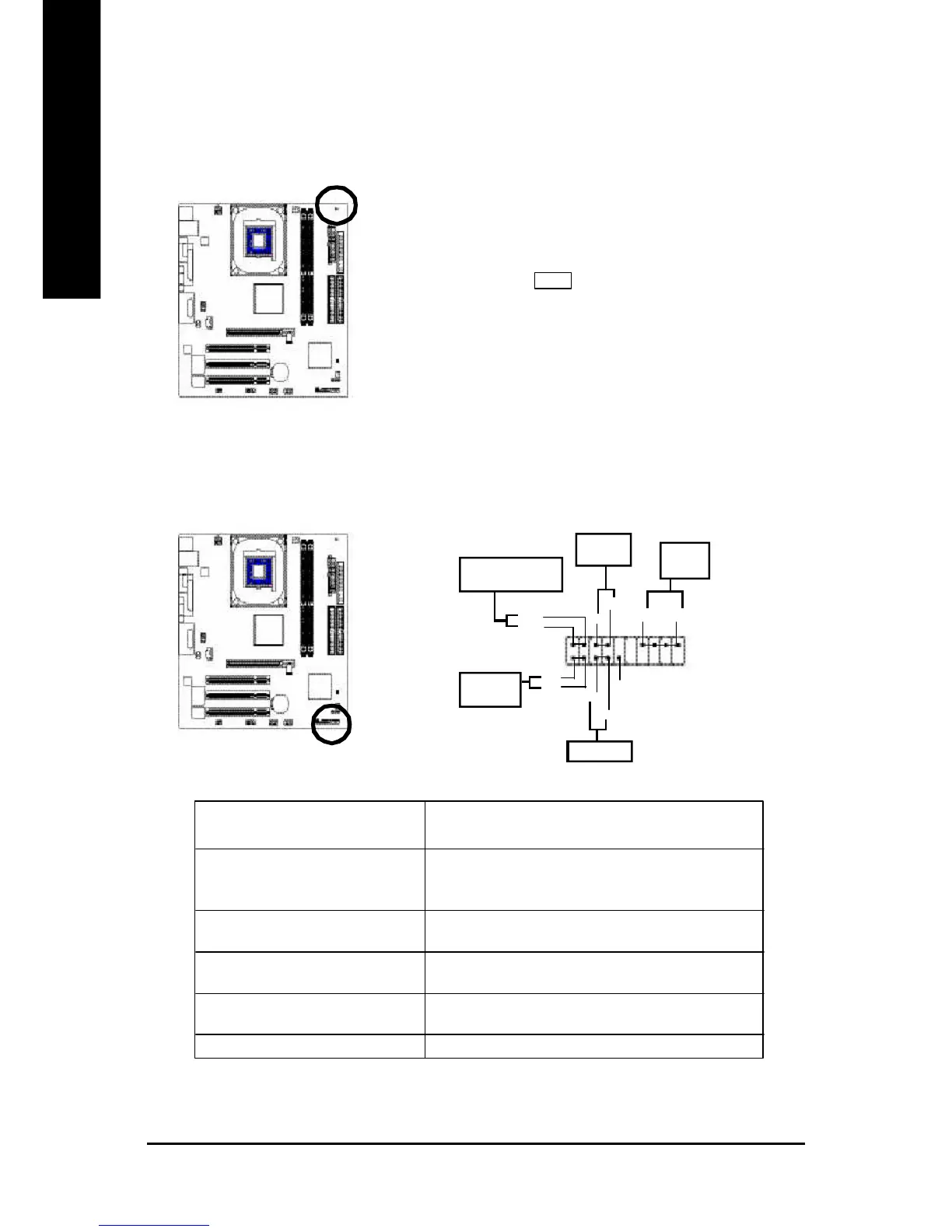
7) DIMM_LED
Do not remove memory modules while DIMM LED is on. It might cause short or other unexpected
damages due to the 2.5V stand by voltage. Remove m emory m odules only when AC Power cord
is disconnected.
+ -
8) F_PANEL (2x10 pins connector)
Please connect the power LED, PC peaker, reset switch and power switch etc of your chassis front
panel to the F_PANEL connector according to the pin assignment above.
HD (IDE Hard Disk Active LED) Pin 1: LED anode(+)
Pin 2: LED cathode(-)
SPK (Speaker Connector) Pin 1: VCC(+)
Pin 2- Pin 3: NC
Pin 4: Data(-)
RST (Reset Switch) Open: Normal Operation
Close: Reset Hardware System
PW (Soft Power Connector) Open: Normal Operation
Close: Power On/Off
MPD(Message LED/Power/ Pin 1: LED anode(+)
Sleep LED) Pin 2: LED cathode(-)
NC NC
SP K -
SPK+
20
Speaker
Connector
1
19
IDE Hard Disk
Active LED
Reset Switch
2
1
Soft Power
Connector
1
MPD+
MPD-
Message LED/Power/
Sleep LED
PW-
PW+
1
HD+
HD-
1
RST+
RST-
NC
1
 Loading...