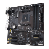
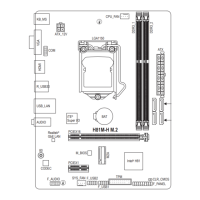
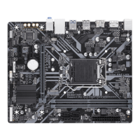
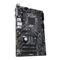
- 21 - Hardware Installation
In addition to the default speakers settings, the ~ audio jacks can be recongured to perform
different functions via the audio software. Only microphones still MUST be connected to the default
Mic in jack ( ). Refer to the instructions on setting up a 2/4/5.1/7.1-channel audio conguration in
Chapter 5, "Conguring 2/4/5.1/7.1-Channel Audio."
Line In/Mic In Jack (Blue)
The line in/Mic in jack. Use this audio jack for line in devices such as optical drive, walkman, microphone,
etc.
Line Out Jack (Green)
The line out jack. Use this audio jack for a headphone or 2-channel speaker. This jack can be used to
connect front speakers in a 4/5.1/7.1-channel audio conguration.
Optical S/PDIF Out Connector
This connector provides digital audio out to an external audio system that supports digital optical audio.
Before using this feature, ensure that your audio system provides an optical digital audio in connector.
Center/Subwoofer Speaker Out Jack (Orange)
Use this audio jack to connect center/subwoofer speakers in a 5.1/7.1-channel audio conguration.
Rear Speaker Out Jack (Black)
Use this audio jack to connect rear speakers in a 4/5.1/7.1-channel audio conguration.
Side Speaker Out Jack (Gray)
Use this audio jack to connect side speakers in a 7.1-channel audio conguration.
 Loading...