Hardware Installation - 20 -
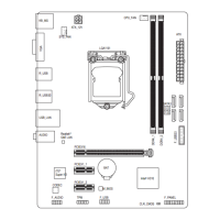
1-7 Back Panel Connectors
USB 2.0/1.1 Port
The USB port supports the USB 2.0/1.1 specication. Use this port for USB devices such as a USB
keyboard/mouse, USB printer, USB ash drive and etc.
PS/2 Keyboard/Mouse Port
Use this port to connect a PS/2 mouse or keyboard.
CPU Overclcking Button
Press this button to overclock your CPU. To return to the defaults, press this button again.
BIOS Switch Button
The button allows users to easily select a different BIOS for boot up or overclocking, helping to reduce BIOS
failure during overclocking. Press the button to switch between the main BIOS and backup BIOS. The green
LED indicates the main BIOS is active and the blue LED indicates the backup BIOS is active.
Clear CMOS Button
Use the clearing CMOS button to clear the CMOS values (e.g. date information and BIOS congurations) and
reset the CMOS values to factory defaults when needed.
eSATA/USB Combo Connector
This connector supports SATA 6Gb/s and USB 2.0/1.1 specication. Use the port to connect an external
SATA device or a SATA port multiplier. The Marvell 88SE9172 chip supports RAID function. Refer to
Chapter 5, "Conguring SATA Hard Drive(s)," for instructions on conguring a RAID array. Or use this port
for USB devices such as a USB keyboard/mouse, USB printer, USB ash drive and etc.
USB 3.0/2.0 Port
The USB 3.0 port supports the USB 3.0 specication and is compatible to the USB 2.0/1.1 specication.
Use this port for USB devices such as a USB keyboard/mouse, USB printer, USB ash drive and etc.
RJ-45 LAN Port
The Gigabit Ethernet LAN port provides Internet connection at up to 1 Gbps data rate. The following
describes the states of the LAN port LEDs.
When removing the cable connected to a back panel connector, rst remove the cable from your •
device and then remove it from the motherboard.
When removing the cable, pull it straight out from the connector. Do not rock it side to side to •
prevent an electrical short inside the cable connector.
 Loading...