- 29 - Hardware Installation
12) F_USB1/F_USB2/F_USB3 (USB 2.0/1.1 Headers)
The headers conform to USB 2.0/1.1 specication. Each USB header can provide two USB ports via an
optional USB bracket. For purchasing the optional USB bracket, please contact the local dealer.
Do not plug the IEEE 1394 bracket (2x5-pin) cable into the USB 2.0/1.1 header. •
Prior to installing the USB bracket, be sure to turn off your computer and unplug the power cord •
from the power outlet to prevent damage to the USB bracket.
When the system is in S4/S5 mode, only the USB ports routed to the F_USB1 header can support
the ON/OFF Charge function.
Pin No. Denition
1 Power (5V)
2 Power (5V)
3 USB DX-
4 USB DY-
5 USB DX+
6 USB DY+
7 GND
8 GND
9 No Pin
10 NC
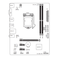
13) F_USB30 (USB 3.0/2.0 Header)
The header conforms to USB 3.0/2.0 specication and can provide two USB ports. You can also install
the included 3.5" front panel into a free 3.5" drive bay of your chassis and connect the USB cable from the
3.5" front panel to this header.
Pin No. Denition Pin No. Denition
1 VBUS 11 D2+
2 SSRX1- 12 D2-
3 SSRX1+ 13 GND
4 GND 14 SSTX2+
5 SSTX1- 15 SSTX2-
6 SSTX1+ 16 GND
7 GND 17 SSRX2+
8 D1- 18 SSRX2-
9 D1+ 19 VBUS
10 NC 20 No Pin
F_USB30
F_AUDIO(H)
DB_PORT
F_PANEL(NH) F_PANEL
(H61M-D2)
ACPI_CPT
(GA-IVB)
BIOS_PH
(GA-IVB)
SMB_CPT
(GA-IVB)
CLR_CMOS
CI
DIS_ME
GP15_CPT
(GA-IVB)
XDP_CPU
XDP_PCH
(GA-IVB)
TPM
w/housing
Voltage measurement module(X58A-OC)
PCIe power connector (SATA)(X58A-OC)
DIP
1 2 3
DIP
1 2 3
DIP
1 2 3
DIP
123
1
1
1
1
BIOS Switcher (X58A-OC)
PWM Switch (X58A-OC)
M_SATA
PWM Switch (SW1)(X79-UD7)
DIP
1 2 3 4 5
 Loading...