- 51 - Motherboard Components
Chapter 4 Motherboard Components
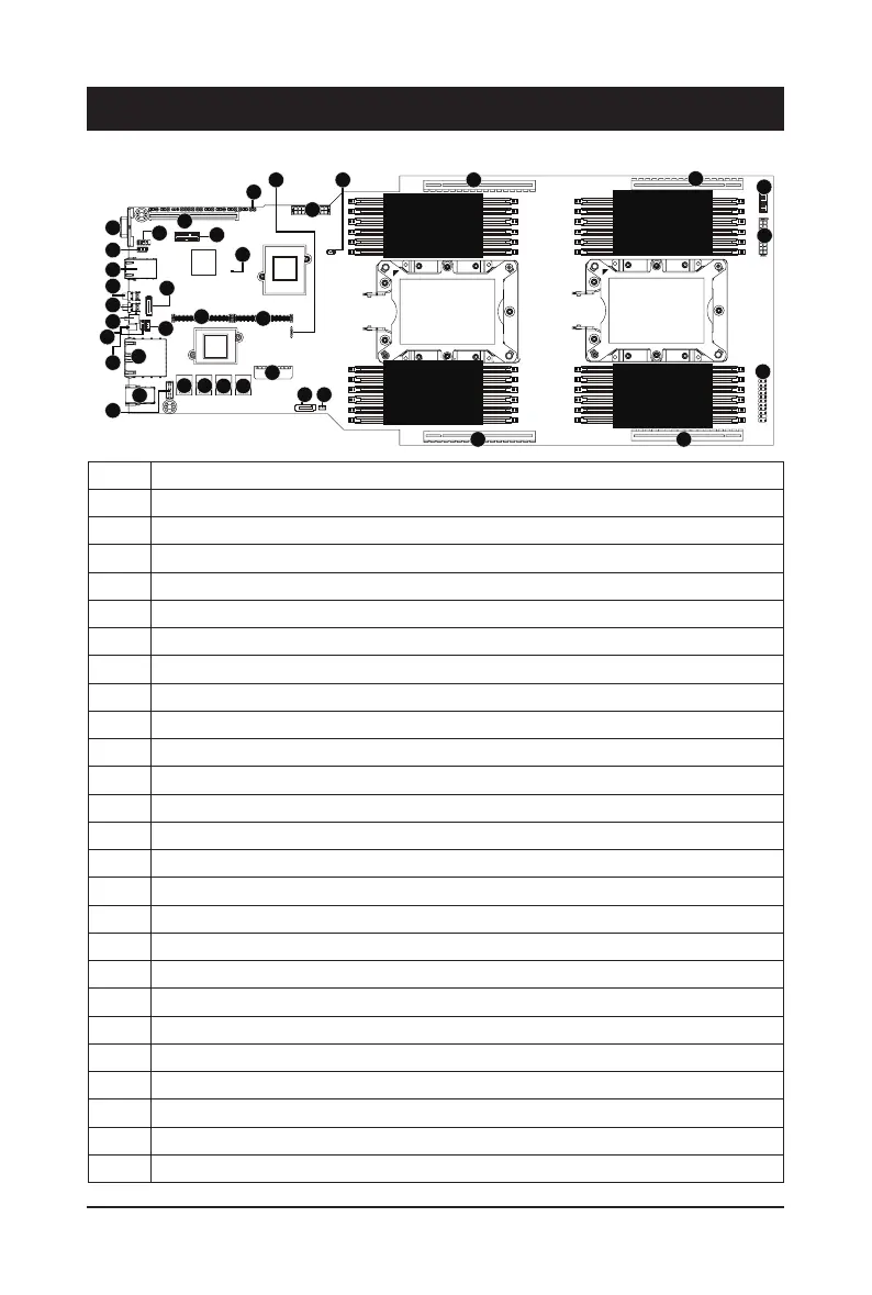
4-1 Motherboard Components
Item Description
1 Rear VGA port
2 Serial port connector
3 12V Standby power connector (for system power)
4 10/100/1000 Server management LAN port
5 Power button with LED
6 sSATA 6Gb/s connector #1
7 ID button with LED
8 Reset button (top)/ NMI button (bottom)
9 System status LED
10 VMD RAID upgrade key
11 IPMB connector
12 GbE LAN ports
13 USB 3.0 ports
14 HDD back plane board connector
15 SlimLine 4i connector #0 (support NVMe)
16 SlimLine 4i connector #1 (support NVMe)
17 SlimLine 4i connector #1 (SATA 6Gb/s signal/for SATA #0 - #3))
18 SlimLine 4i connector #2 (SATA 6Gb/s signal/for SATA #4 - #7))
19 2 x 9-pin main power connector (for primary CPU)
20 sSATA 6Gb/s connector #0 (supports SATA DOM)
21 SATA DOM support power connector for sSATA port #0
22 PCIe x16 slot #2
23 PCIe x16 slot #4
24 Front panel header (primary)
25 2 x 9-pin main power connector (for secondary CPU)
21
DIMM_P0_F1
DIMM_P0_E0
DIMM_P0_E1
DIMM_P0_D0
DIMM_P0_D1
DIMM_P0_F0
DIMM_P0_A0
DIMM_P0_B1
DIMM_P0_B0
DIMM_P0_C1
DIMM_P0_C0
DIMM_P0_A1
DIMM_P1_I1
DIMM_P1_H0
DIMM_P1_H1
DIMM_P1_G0
DIMM_P1_G1
DIMM_P1_I0
DIMM_P1_J0
DIMM_P1_K1
DIMM_P1_K0
DIMM_P1_L1
DIMM_P1_L0
DIMM_P1_J1
CPU1
(Secondary)
&38
3ULPDU\
1
3
2
4
5
7
6
9
8
10
11
12
13
14
15 16
17 18
19
20 21
24
22
282931
32
33
34
35
36
17
30
23
25
26
 Loading...