- 18 -
Hardware Installation
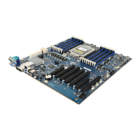
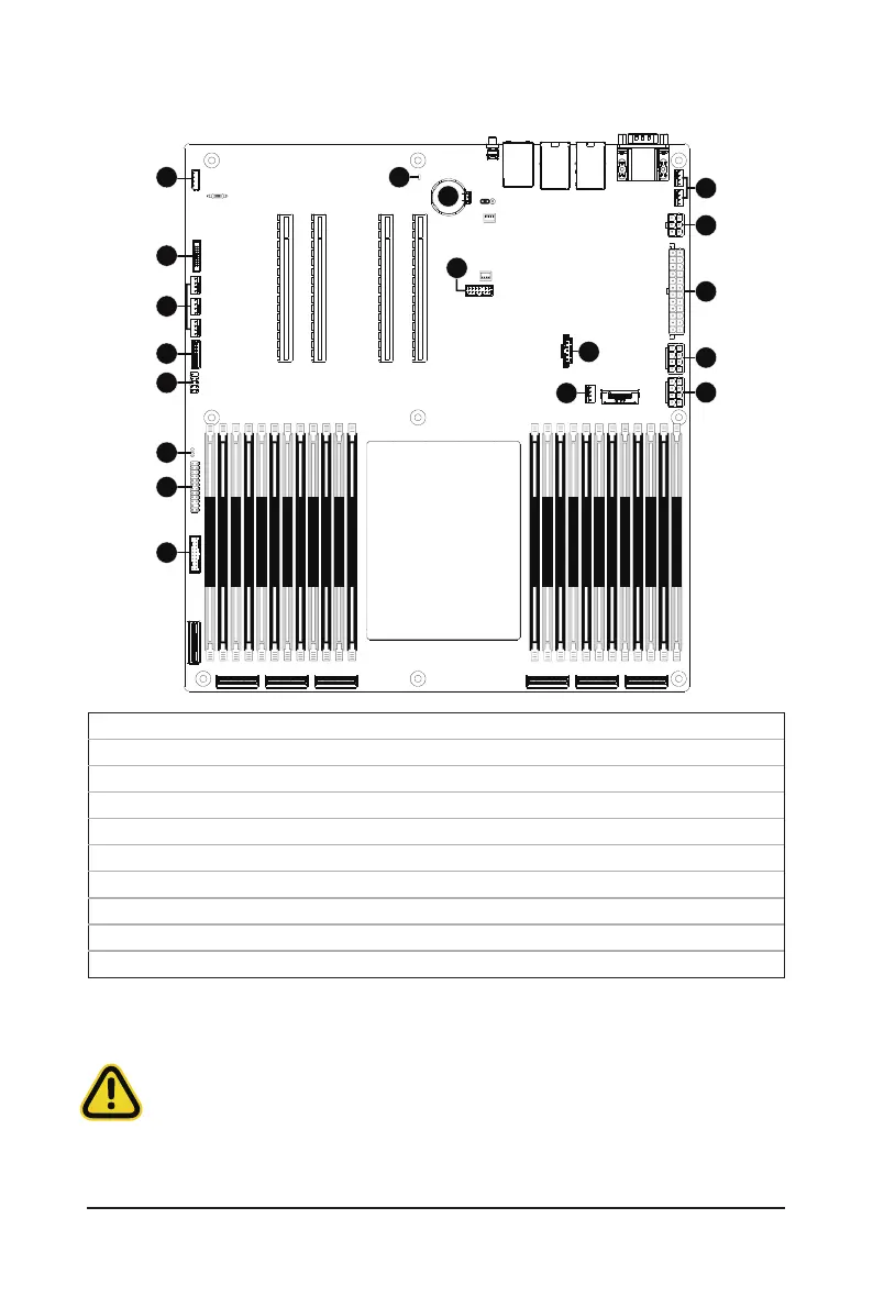
1-7 Internal Connectors
Read the following guidelines before connecting external devices:
•
First make sure your devices are compliant with the connectors you wish to connect.
•
Before installing the devices, be sure to turn off the devices and your computer. Unplug the power
cord from the power outlet to prevent damage to the devices.
•
After installing the device and before turning on the computer, make sure the device cable has
been securely attached to the connector on the motherboard.
1) ATX1 11) FP_1
2) P12V_AUX1 12) BP_1
3) P12V_AUX2 13) SPI_TPM
4) P12V_PCIE 14) IPMB
5) CPU0_FAN1 15) CN_NSCI
6) SYS_FAN1/SYS_FAN2/SYS_FAN3 16) LED_BMC
7) SYS_FAN4/SYS_FAN5 17) BAT
8) PMBUS 18) CASE_OPEN
9) F_USB3
10) F_USB2
21
CPU0
DIMM_P0_A1
DIMM_P0_D1
DIMM_P0_C0
DIMM_P0_C1
DIMM_P0_B0
DIMM_P0_B1
DIMM_P0_A0
DIMM_P0_D0
DIMM_P0_E1
DIMM_P0_E0
DIMM_P0_F1
DIMM_P0_F0
DIMM_P0_G0
DIMM_P0_G1
DIMM_P0_K0
DIMM_P0_K1
DIMM_P0_J0
DIMM_P0_J1
DIMM_P0_I0
DIMM_P0_I1
DIMM_P0_H0
DIMM_P0_H1
DIMM_P0_L0
DIMM_P0_L1
1
3
4
5
6
2
7
8
9
10
14
11
15
16
18
17
12
13
 Loading...