User Guide
GD32450Z-EVAL
34
5.17. CAN_Network
5.17.1. DEMO purpose
This demo includes the following functions of GD32 MCU:
Learn to use the CAN0 communication between two boards
Learn to communicate with PC by USART
5.17.2. DEMO running result
This example is tested with two GD32F450Z-EVAL boards. Jump the JP13 to USART
and P2, P3 to CAN0 with the jumper cap. Connect L pin to L pin and H pin to H pin of
JP11 on the boards for sending and receiving frames. Download the program
<17_CAN_Network> to the two EVAL boards, and connect serial cable to COM0. Firstly,
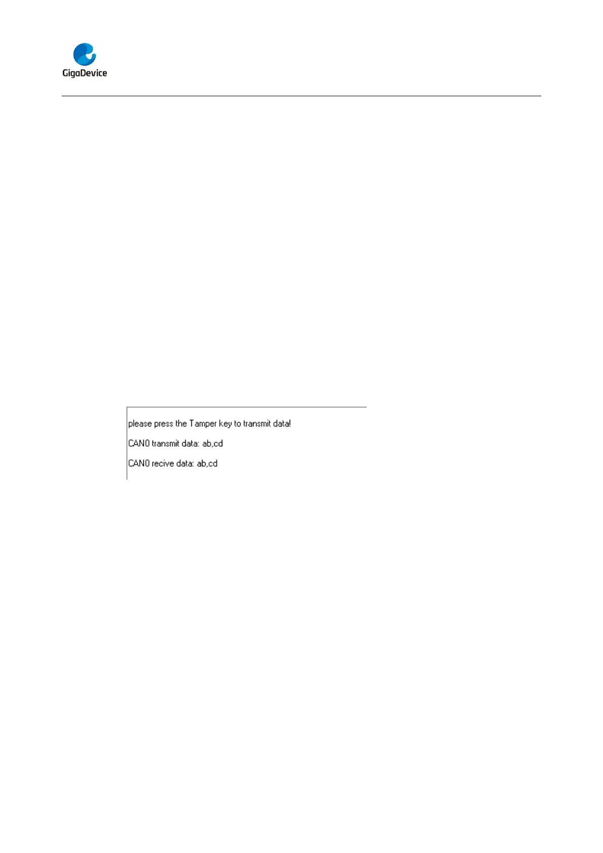
the COM0 sends “please press the Tamper key to transmit data!” to the HyperTerminal.
The frames are sent and the transmit data are printed by pressing Tamper Key push
button. When the frames are received, the receive data will be printed and the LED2 will
toggle one time.
The output information via the serial port is as following.
5.18. RCU_Clock_Out
5.18.1. DEMO purpose
This demo includes the following functions of GD32 MCU:
Learn to use GPIO control the LED
Learn to use the clock output function of RCU
Learn to communicate with PC by USART
5.18.2. DEMO running result
Jump the JP5 to USART with the jumper cap, and download the program
<18_RCU_Clock_Out> to the EVAL board and run. Connect serial cable to COM0, open
the HyperTerminal. When the program is running, HyperTerminal will display the initial
information. Then user can choose the type of the output clock by pressing the TAMPER
button. After pressing, the corresponding LED will be turned on and HyperTerminal will
 Loading...


