Page 2 MDE-5265E BRCM2.x Installation and Upgrade Instructions · April 2021
Introduction
Required Tools
The following tools and materials are required for installing BRCM2.x:
• Needle-Nose Pliers
• Wire Strippers
• Phillips
®
Screwdriver
• Diagonal Cutters
• Wire Nuts
• Tools to Install Conduit
Required Reading
Before performing the installation, read, understand, and follow:
• This manual
• NFPA 30A, The Automotive and Marine Service Station Code
• NFPA 70
®
, The National Electric Code (NEC
®
)
• Applicable federal, state, and local codes and regulat
ions
Failure to do so may adversely affect the
safe use and operation of the equipment.
Note: To ensure valid warranty, this kit must be in
stalled by a Gilbarco-trained ASC.
NEC 514.11 Compliance
Provided that the BRCM2.x is powered from emergency-disconnected AC power and all field
wiring connections go through the field wiring board, it meets the low-voltage disconnect
requirement of NEC section 514.11 as it has a clearly identified switch inside the BRCM2.x to
disconnect all two-wire circuits. The BRCM2.x has a provision for a locking hasp, to provide
a lockout/tagout function.
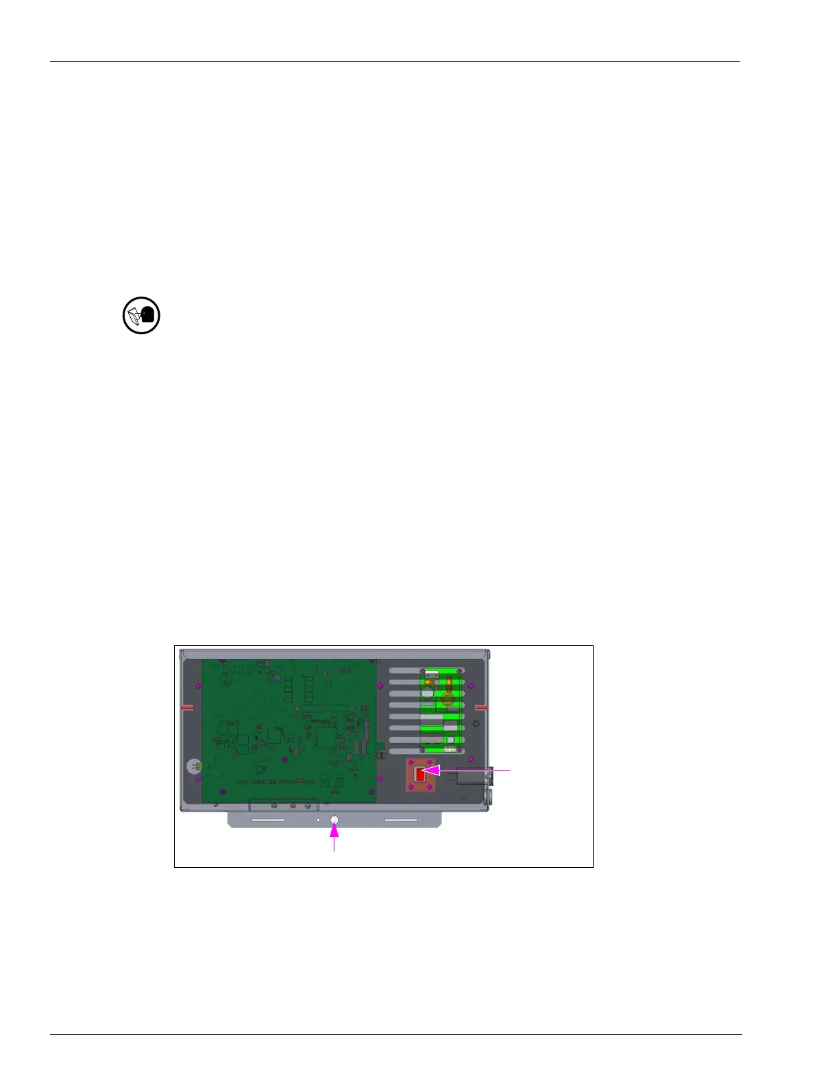
Figure 1: Locking Hasp Provision and Lockout/Tagout Power Switch
Locking Hasp
Lockout/Tagout
Power Switch