MDE-5265E BRCM2.x Installation and Upgrade Instructions · April 2021 Page 3
Introduction
Theory of Operation
Note: For site connectivity diagrams, refer to Figure 2, Figure 3 on page 4, and Figure 4 on
page 4.
If the upgraded D-Box or factory-shipped BRCM2.x ends in “12” or “22”,
they include
two-wire distribution boards, allowi
ng the communication to the dispenser/pump(s) to occur
over the current loop(s). The lid portion of the BRCM2.x assembly contains the high-speed
signal source that is merged with the dispenser/pump or CRIND
®
current loop.
For Passport
™
Point of Sale (POS), the BRCM2.x or upgraded D-Box will be communicating
over the existing current-loop connection.
For non-Passport POS, the BRCM2.x or upgraded D-B
ox will be communicating over the
dispenser/pump current-loop connection. Identify the D-Box or D-Box boards communicating
to the dispensers/pumps and mark those wire sets.
Note: Do not change
the CRIND wiring.
Like previous D-Boxes, the BRCM2.x or upgraded D-Box will use D-Box boards. In a dual
b
oard solution, the boards may have the following configurations:
• One board talking dispenser/pump
or CRIND protocol message streams and another board
independently talking dispenser/pump or CRIND protocol message streams.
• Two boards communicating to up to 16 dispensers/pumps using the same me
ssage stream
(viable for CRIND communications only).
Site Connectivity Diagrams
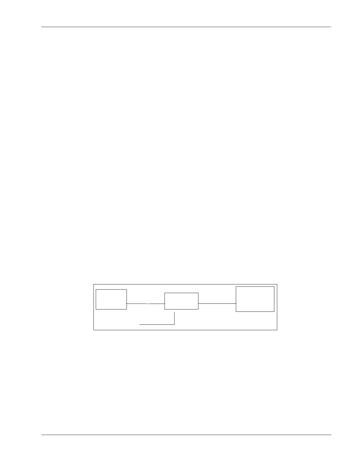
Figure 2 shows a non-EMV Passport configuration. Current loop boards are required in the
BRCM2.x (model numbers ending with “12” or “22”). For additional det
ails on this
configuration, refer to Figure 36 on page 36. The PA0435 models has a single combined D-
box and a field wiring board; for more detail on this configuration, refer to
Figure 39 on page 39.
Figure 2: Passport (Expandable to Dual Boards)
Passport
BRCM2.x
DCM2.x board,
configured in
MOC mode
Ethernet
®
Two-wire with
CRIND Protocol
CRIND
Two-wire +
High-speed
Figure 3 and Figure 4 on page 4 show a non-EMV generic configuration. For this
configuration, the model number must end with 22. For additional details on this
co
nfiguration, refer to Figure 35 on page 35. The PA0435 models has a single combined D-
box and a field wiring board. The CCP board DCM2.x is also replaced with HCM board; for
more in
formation on this configuration, refer to Figure 38 on page 38.
 Loading...