MDE-5265E BRCM2.x Installation and Upgrade Instructions · April 2021 Page 23
Upgrading to BRCM2.x
Connecting Field Wiring
There are multiple 8-to-8 pin connectors supplied that connect the field wiring board to the
D-Box boards. Use of these connectors will vary if
one D-Box board is used for
dispenser/pump and the other boa
rd is used for CRIND (see Figure 18 and Figure 19 on
page 24).
To connect the field wiring board to
the D-Box boards, proceed as follows:
1 If the box is part number PA04222000202/202B/002B (for being used with dedicated wiring),
proceed to step 2. If the D-Box connects to a Passport POS, connect all supplied con
nectors
between the top of the M14881A001 Printed Circuit Assembly (PCA)
Field Wiring Board and
the D-Box board(s).
~OR~
If the D-Box connects to a non-Passport POS and the
re are multiple D-Box boards, only
connect the top of the M14881A002 PCA Field Wiring Board to the D-Box board
communicating to the dispenser/pump current loop.
2 Connect the field wiring connectors to the M14881A002 PCA Field Wiring Board
(see Figure 18 and Figure 19 on page 24).
For non-Passport POS with dispenser/pump and CRIND connected communicat
ions in the
same D-Box, connect the dispenser/pump field wiring connections to the bottom of the field
wiring board and connect the CRIND communication wires to the D-Box board.
~OR~
Connect all field wiring connectors to the bottom of the fi
eld wiring board.
After this operation, all dispenser/pump communication are
connected either directly to the
field wiring board or to a D-Box board via the M14881A002 PCA Field Wiring Board.
Note: All dispensers that have the DC
M2.x board, have either the pump or CRIND connected
to the field wiring board to receive the high-speed signal. A generic CRIND or a Legacy
dispenser connects directly to the D-Box board because these configurations cannot
accept the high-speed signal.
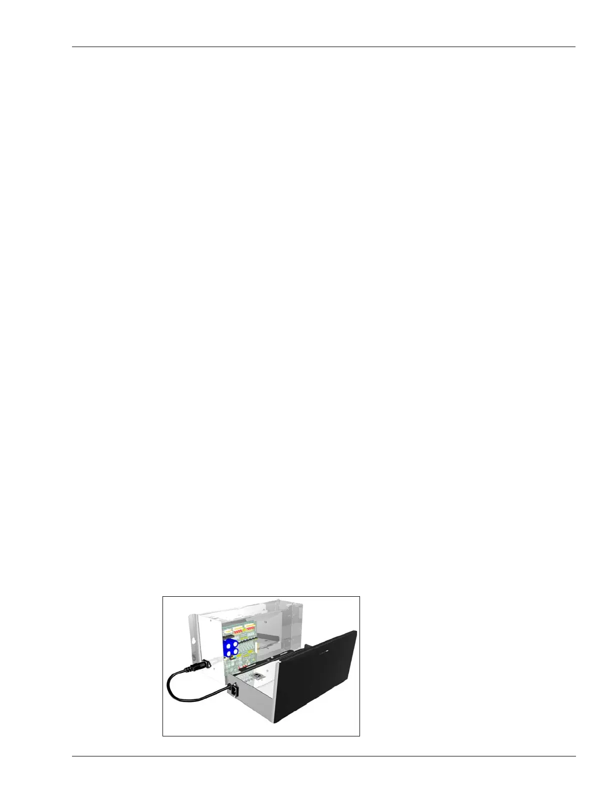
3 Hold the lid assembly close to the D-Box [the lock plate has two tabs to allow the lid assembly
to rest on the tabs (see Figure 17)] and connect the lid cables to the P400 and P416 connectors
between the lid assembly and the M14881A002 PCA
Field Wiring Board
(see Figure 18 on page 24).
Figure 17: Lid Assembly Open
Note: This figure is an example only.
 Loading...