17
Hydraulic Cylinder Inspection and Repair
The hydraulic cylinders apply force to the clamp rods,
which draw the Vibrating Unit Assembly parts together�
If the machine loses clamping pressure during operation,
and/or if hydraulic oil must be frequently added, inspect the
hydraulic cylinders for wear�
Disconnect power supply before
servicing or cleaning.
DO NOT plug in or operate the
Testing Screen without all covers installed.
When working with the hydraulic
cylinders, take care NOT to score surfaces where
seals must be maintained.
To inspect a hydraulic cylinder for wear:
1. Unplug or otherwise disconnect the Testing Screen from
its power source, and lock out the connection�
2. Drain the hydraulic system. See Draining and Relling
the Hydraulic System on page 14�
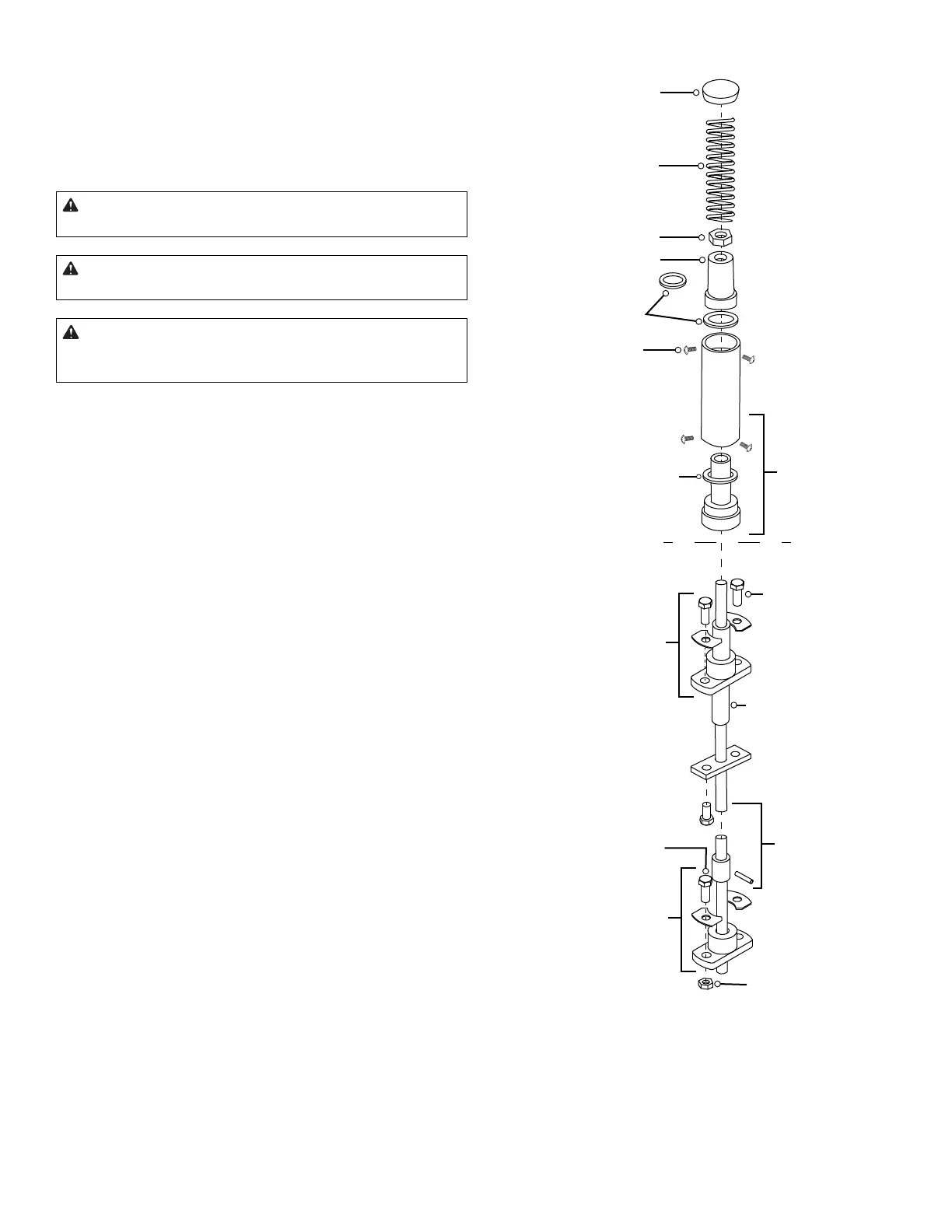
3. Remove the three screws securing the cylinder cap
(Fig� 8)� The spring is compressed inside the cylinder by
the cap, so caution is required� Keep pressure on the
cap with your hand as you remove the three screws�
4. Release the pressure on the cap slowly so that the
compressed spring does not eject suddenly� Remove the
cap and spring�
5. Remove the side access panel near the machine’s base�
6. Grasp the lower section of hydraulic clamp rod with vice
grips and hold it steady while unscrewing the clamp rod
hex jam nut�
7. Pull the rest of the cylinder up and o the clamp rod.
8. Examine the piston and the two quad rings: One ts in a
groove on the piston ange, and the other ts inside the
piston. Replace the quad rings if you nd hydraulic oil
above the ange on the piston.
NOTE: It should NOT be necessary to disassemble the
cylinder from its base� Cylinder O-rings rarely need
to be replaced�
9. If cylinder O-ring replacement is necessary, use a 3/16in
drift punch to drive each of the roll pins through to the
center hole until they fall out� Remove the old O-ring�
Apply a small amount of hydraulic oil to the new O-ring,
and install it� Reassemble�
Cylinder Cap
Spring
Quad Ring Set
Cylinder O-ring
Clamp Rod
Hex Jam Nut
Hydraulic Cylinder
Piston
Cylinder Cap
Screws
Cylinder Base/
Sub-assembly
Upper Guide
Bearing Assembly
Upper Guide
Bearing Screw
Upper Guide
Bearing Sleeve
Hydraulic Clamp
Rod Collar
and Pin
Lower Guide
Bearing Assembly
Lower Guide
Bearing Screw
Lower Guide
Bearing Stop Nut
Fig. 8: TS-1 and TS-3 Hydraulic Cylinder