CONTENTS
Basic System Overview ………………………………………………………………………………………….… 4
Installation Instructions …………………………………………………………………………………………... 5
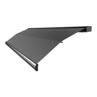
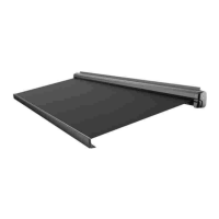
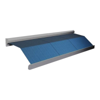
Product Description ……………………………………………………………………………………………….… 6
Tools Required ……………………………………………………………………………………………………….. 6
A. Unpacking ………………………………………………………………………………………………………. 7
B. Layout and Mounting the Brackets ……………………………………………………………………. 8
Awning Bracket placement chart …………..…………………………………………………………………. 9
C. Mounting the Awning …………………………………………………………………………………….. 10
D. Motion Sensor …………………………………………………………………………………………….…. 11
Testing and Adjustments ………………………………………………………………………………………. 12
A. Adjusting Motor Limit Switches …………………………………………………………………... 12-13
B. Adjusting Pitch ………………………………………………………………………………………………. 14
C. Testing the Motion Sensor ……………………………………………………………………………… 15
D. Adjusting the Lead Rail ………………………………………………………………………………….. 15
Troubleshooting Guide ……………………………………………………………………………………… 16-18
Exploded Diagram ……………………………………………………………………………………………… 19
Component Identification ………………………………………………………………………………….. 20-21
THE G–LINK SYSTEM
The G-Link motors and control modules provided by Girard Systems communicate by
use of RF signals on a frequency of 433.92 MHZ. This eliminates the need for wiring
and the drilling of holes in the vehicle. These components must be electronically
matched, programmed or paired before use. This is usually done at the Girard Systems
factory. Should the need arise for the user to pair a device with the motor controller
they must refer to the appropriate manual for the devices applicable to their particular
installation.