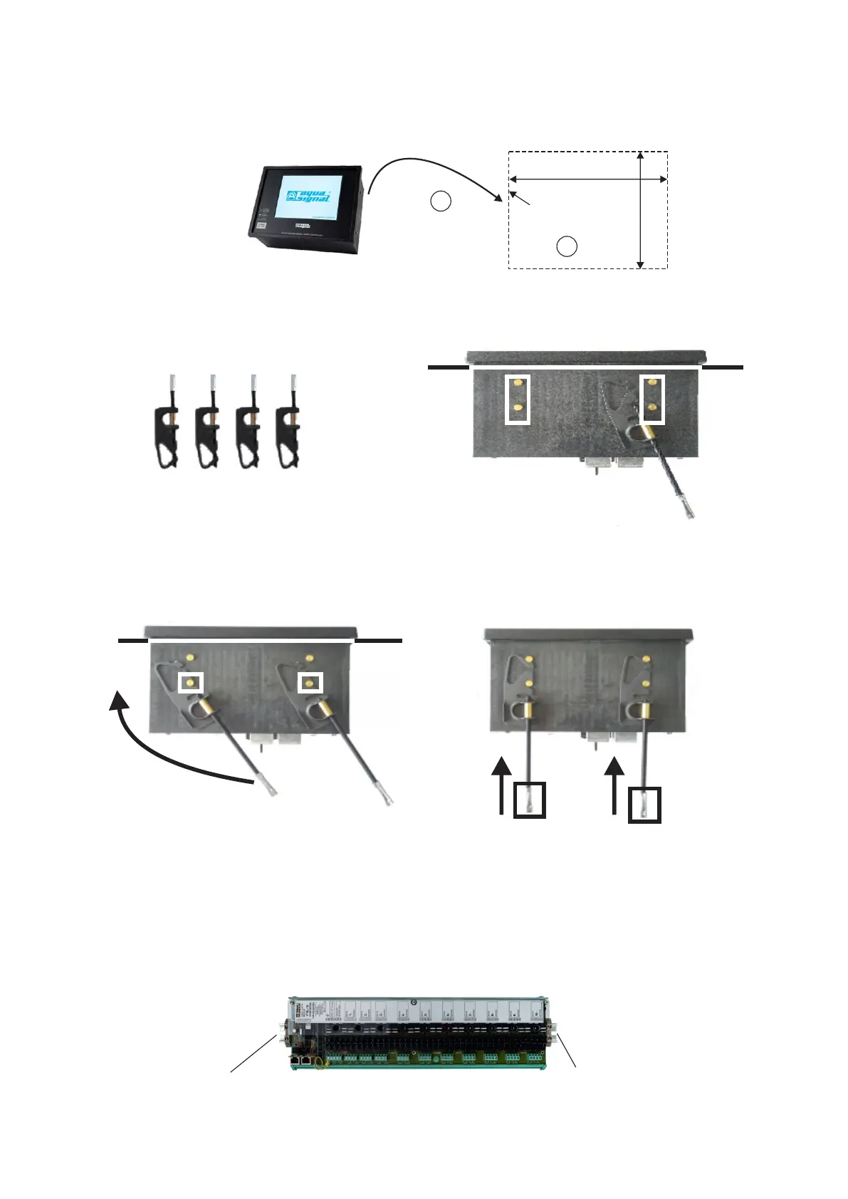
186
138
PANEL
CUT-OUT
3.3 Mounting
3.3.1 Mounting of main unit
Make cut-out according drawing bellow (1) and put main unit into cut-out (2).
2
Mounting clamps
Clasp pin
console
4. Mounting clamps are inserted in clasp pins located on side of main conrol unit (pls. check photo)
5. Place first hole of mounting clamp into clasp pin and rotate until second hole is fixed (pls. check photo)
6. Screw mounting clamp until screw reaches console.
7. Check if main unit is fixed firmly
console
3.3.2 Mounting of power supply and input modules
1. Modules are mounted on din rail TS 35. Rail must be fixed with 2 bolts M6 (pls. check photo).
for bolts M6
for bolts M6
3. For mounting main unit to console 4 pcs of mounting clamps are provided (pls. check photo)
1
13
 Loading...