Battery Instructions
This system will accommodate the B12-100
maintenance free (AGM) battery. To double the
runtime of the backup system, two of the same
model batteries can be connected together. The
batteries should be of similar age. Connecting
an old and new battery together will not charge
be explained below.
Note: The battery will not run the primary pump.
CAUTION
• The use of automotive batteries is NOT
recommended. Automotive batteries are
not designed for this application. They will
only run the pump for a short time and will
have a shorter life than a standby battery.
• The internal construction of some wet-cell
batteries may not be compatible with this
system. The use of a Pro Series B12-100
battery is HIGHLY recommended.
System Connections
!
DANGER
Risk of electrical shock or battery explosion,
which can cause serious injury or death.
Wear eye protection. Work in a well-
ventilated area. DO NOT smoke or allow a
spark or ame in the vicinity of the battery.
Avoid dropping metal tools on the battery.
Review the safety instructions on page 2.
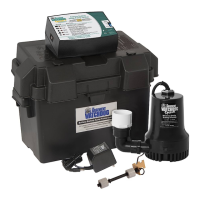
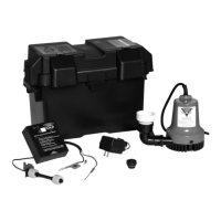
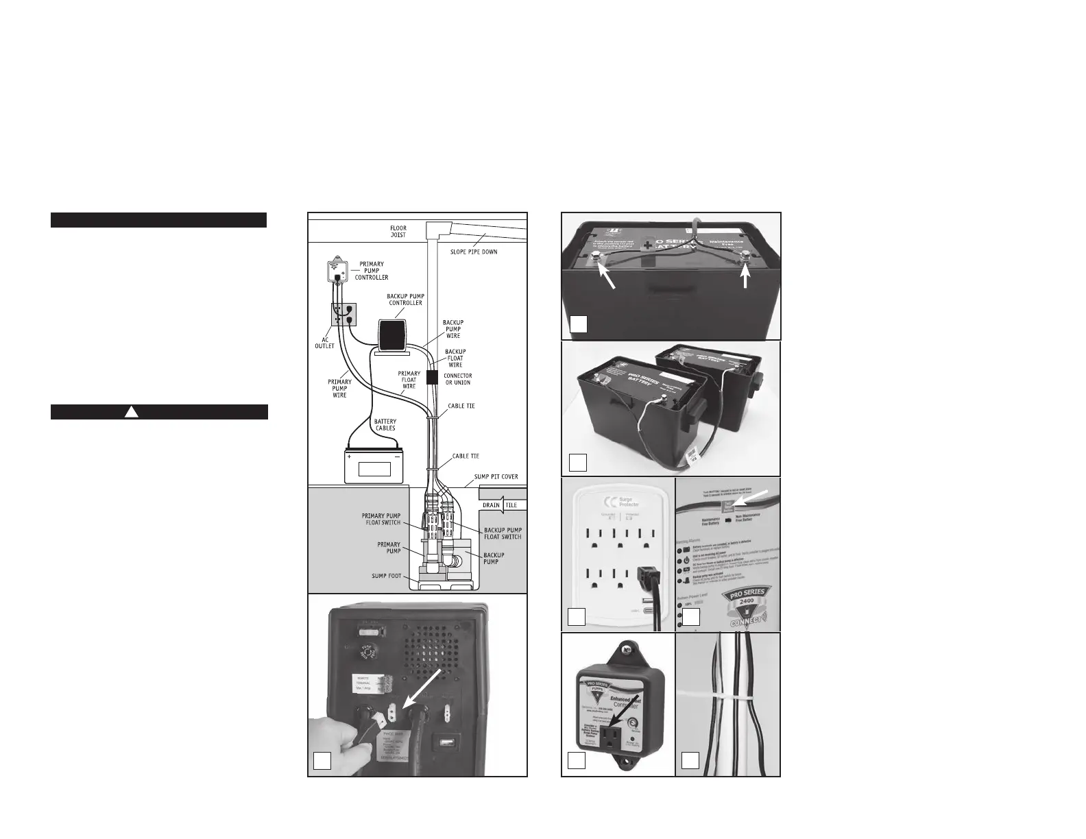
Position the backup system control unit in
AC power outlet, and the pump cable and the
pit. Position the unit in a well-ventilated area.
Do not place anything on top of the battery.
Do not place anything on top of the control
unit. (Diagram C)
1. Connecting the backup pump: Remove
the security tag from the pump and plug
the pump wires into the pump connector
on the back of the control unit.
2. Connecting the battery: Remove the
bolts from the hardware bag. Remove the
security tag from the battery cables. Attach
the battery cables to the battery—the RED
wire to the POSITIVE (+) bolt and the
BLACK wire to the NEGATIVE (-) bolt. Screw
the bolts into the battery terminals. Slide
the switch on the front of the backup
controller to the type of battery being used
with the system.
3. Connecting two batteries: If you are
connecting two batteries to the system,
before you screw in the bolts, connect
the parallel jumper cable (Model PJC) to
the two batteries—the RED wires to the
POSITIVE (+) posts and the BLACK wires
to the NEGATIVE (-) posts of each battery.
NEVER attach one end of the positive wire
to the positive post and the other end of
the positive wire to the negative post on
the other battery.
4. Connecting the backup controller:
Immediately plug the AC power cord from
the backup control unit into a grounded
AC wall outlet. (A surge protector that
protects all three pins on the power plug is
recommended - backup system only.) You
will have 10 seconds before the “Power
failure” alarm will sound. The alarm will
silence once the unit is plugged into the
wall.
5. If any of the alarms are sounding, press
the RESET button on the front of the
control panel for one (1) second.
6. Secure the cover on the battery box by
the front and back of the box.
7. Connecting the primary pump: Mount the
Enhanced controller using the 2 through
located on the top and bottom tabs of
the controller. The controller should be
1' from the outlet. Plug the controller
into a properly grounded 3-prong outlet.
Then plug the primary pump into the
receptacle on the controller. Using a
the front of the controller to select the
number of seconds that the primary pump
can be adjusted from 5-45 seconds. The
manufacturer default is about 10 seconds.
8. For a neater installation, secure the cables
from the controllers to the discharge pipe
in several places with additional cable ties.
Make sure the wires are not touching each
other or overlapping each other.
9. After the initial installation, be sure to
sump with water and observing the pump
through several full cycles. The primary
pump should run for 10 seconds after the
10. A pit cover is recommended for all
installations as a safety measure, and to
prevent debris from falling into the pit.
Place the cover on top of the pit making
sure not to pinch or crimp the pump wires
with the cover. The pit cover usually has
an existing hole that will allow the cords
to be passed through it, or you can drill a
hole in the cover.
Page 5
Glentronics, Inc. 800.991.0466
www.stopooding.com
Power On
(when ashing)
12 Amps
Maximum
10
45
Enhanced Float
Controller
Consider a Pro Series
Battery Backup
Sump Pump System
Adjust pump timer from 5-45 seconds
using a at head screw driver.
Seconds
Diagram C
1
3
4
7
5
8
Negative
Bolt
Positive
Bolt
2
 Loading...