Installing the Pipe and Pump
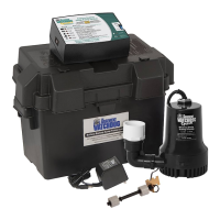
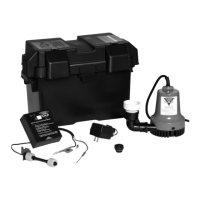
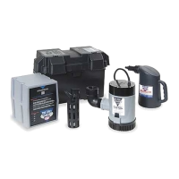
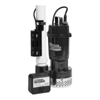
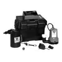
The Pro Series combination system is compact
It measures 17
1
/8
stand to the top of the wye connector, where it
will be attached to the discharge pipe.
Use a pit that conforms to all local codes, and
check the code to see if a gate valve or ball valve
is required.
The path of the existing
vertical discharge pipe to an
exterior wall should have the
shortest path with the fewest
turns. More turns will reduce
the pumping capacity.
The discharge pipe
must be positioned in a
downward slope when it
exits the building, allowing
any remaining water to drain away. Failure to
preventing water from exiting.
free from dirt and debris. If the bottom of the
sump pit is not clean, remove as much of the
debris as possible. The pumps are attached to
a sump foot (stand) to raise them above any
debris. (See Diagram A in column 1 below.)
If you are replacing an old sump pump, unplug
the pump from the outlet.
1. Remove the check valve or rubber union.
(Refer to photo 1 at right.) Discard the
check valve. The Pro Series system contains
built-in check valves, so the old check valve
will not be needed. If the existing system
is installed without a check valve or rubber
union, saw the pipe apart above the sump
pit. (Refer to the diagram in illustration 3
to the right.)
2. Remove the old pump from the pit, and
unscrew the pipe and pipe adapter from the
pump. You can use this pipe to extend the
discharge pipe, if needed.
3. Measure the distance from the bottom of
the sump pit to the end of the discharge
pipe. Subtract 18
1
/8 (the height of the pump
pipe to that length.
4. (a) Connect this piece to the discharge
pipe by cementing the two pieces together
instructions on the PVC pipe cleaner and
cement.) OR, (b) connect the two pieces of
pipe together with a no-hub coupling.
5. Remove the attached cords and controllers
from the carton and place them next to the
pump system. MAKE SURE THE CORDS AND
CONTROLLERS DO NOT FALL INTO THE
SUMP PIT.
6. Loosen the hose clamps on the no-hub
coupling and slide the coupling up on the
discharge pipe. Slightly tighten the upper
hose clamp.
7. Inspect all of the screws on the hose clamps
of the no-hub couplings (primary and backup
pumps). They should be tight.
8. Lift the combination system by the handle
on the primary pump and lower it into the
sump pit. Make sure it is level.
9.
both be vertical.
10. Position the top of the pump system pipe
so that it is directly below the discharge
pipe. Connect the system with the no-hub
coupling, and tighten the upper and lower
hose clamps. Make sure both the discharge
pipe and the system have ample overlap
within the no-hub coupling.
Page 4
Glentronics, Inc. 800.991.0466
www.stopflooding.com
Power On
(when flashing)
12 Amps
Maximum
10
45
Enhanced Float
Controller
Consider a Pro Series
Battery Backup
Sump Pump System
Adjust pump timer from 5-45 seconds
using a flat head screw driver.
Seconds
17
1
/8
END OF
PIPE
18
1
/
8
"
CUT
PVC TO
THIS
LENGTH
1
2
4b
4a
3
5
10
Diagram A
6
97
8
Lift