REFER TO THE PHOTOS BELOW
1. Unplug the power cord from the wall outlet.
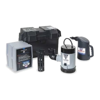
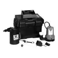
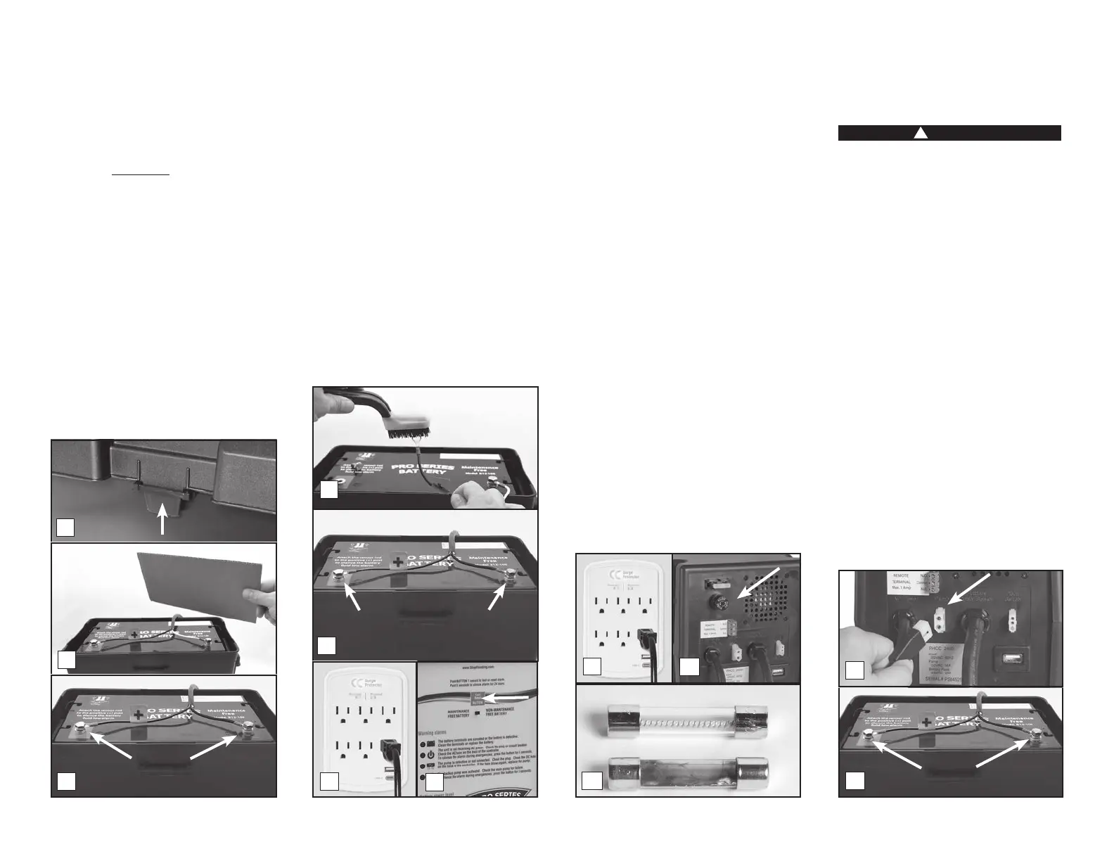
2. Remove the cover of the battery box by
pushing in the tabs on the front and back,
then lifting up.
3. Fan the area around the top of a vented
battery with a piece of cardboard (or
another nonmetallic material) to remove
any hydrogen or oxygen gas that may have
been emitted from the battery.
4. Loosen the bolts and remove the battery
cables. Remove the old battery from the battery
box and place the new battery in the box.
5. Clean any corrosion off of the ring
connectors on the ends of the battery
wires. Use a stiff brush or sandpaper. DO
NOT apply corrosion-resisting sprays or
pads to the terminal rings or bolts after
you have cleaned them, as this could
prevent the battery from charging properly.
6. Replace the battery cables, RED to the
POSITIVE (+) post and BLACK to the
NEGATIVE (-) post. Tighten the bolts.
7. Plug the power cord back into the wall
outlet. (You should provide additional
protection for the backup control unit by
using a surge protector.)
8. Replace the cover on the battery box.
9. If any of the alarms are sounding, press
the RESET button on the front of the
control panel for one (1) second.
CLEANING BATTERY TERMINALS
Refer to REPLACING THE BATTERY (page 6)
follow the same steps without swapping out
the battery as stated in step 4.
2 The unit is not receiving AC power
Power failure can have several causes. The
most common is a power outage by your
electric company. During this emergency, the
Pro Series system will automatically switch
to battery power and protect your basement
You can silence the “AC power failure” alarm
for 24 hours by pressing the RESET button for
but the light will stay on. The system will
continue to operate while the power alarm is
silenced. After 24 hours, the alarm will reset
automatically.
1. If the power is on in the rest of the house,
check the home circuit breaker or fuse box
for failure, and correct the problem.
2. Check the power cord. Make sure it is
securely plugged into the wall outlet. Make
sure the outlet is working properly.
3. The control unit may have received a power
surge. (a) Check the AC fuse located on
the back panel of the control unit. First,
unplug the control unit from the wall outlet.
To check the barrel fuse, push it in and
turn it counter-clockwise then pull it out to
see if the wires in the fuse are intact. (b) If
the wires are burned and broken, replace
the fuse with a 5 Amp glass-barrel fuse,
commonly found at hardware stores and
auto supply stores. Replace the fuse by
pushing it in and turning clockwise. Plug
in the control unit. (You should provide
additional protection for the control unit by
using a surge protector.) If the fuse blows
again, call Glentronics technical support at
800-991-0466.
The control unit must receive 115 volts AC
+/- 5% from the AC outlet. Voltage lower
than 110 volts will activate the power failure
alarm. Lower voltages can be caused by
utility company brownouts or a heavy power
draw from other appliances on the same
circuit. Reduce the number of appliances on
the circuit.
3 DC fuse blown or backup pump defective
!
DANGER
Unplug the main AC pump before servicing
the backup pump to avoid electric shock.
Failure to do so could cause serious injury
or death.
REFER TO THE PHOTOS BELOW
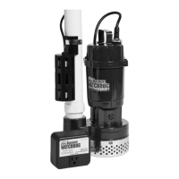
The Pro Series control unit will check the
pump and its wire connections each week
for possible pump failure. The system will
test the pump by running it for 2-3 seconds
to make sure it is operating. The test will not
trigger an alarm. If the “Pump or DC fuse”
alarm sounds:
1. Check the pump plug in the back of the
Check the pump wires to make sure they
are connected securely to the pump plug.
Check the rest of the pump wires for any
possible breaks.
2. If the pump wires are intact, the pump may
be clogged. (a) Disconnect both control
units from the wall outlet, and disconnect
the battery cables. (b) Release the no-hub
coupling, and remove the pumps from the
sump pit. (c) Rinse any debris from the
strainer, and then reconnect the pumps to
the discharge pipe. (d) Connect the control
unit, and the battery cables to the battery—the
Page 7
2
3
5
Remove
4
6
7
9
3a
2
3b
Good
Blown
2a
Remove
1
Negative
Bolt
Positive
Bolt
 Loading...