12
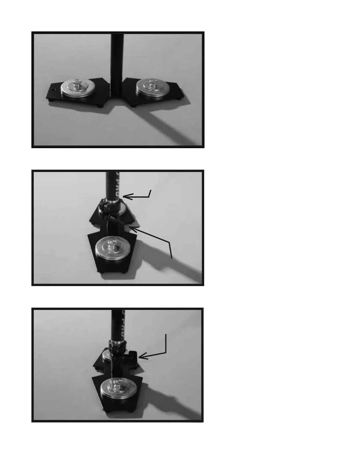
Both COUNTER WEIGHT DISK stacks
should now be secured in place with the
FENDER WASHERS and BRASS
THUMB NUTS as shown in this photo.
Now, insert the TELESCOPING POST
with the attached BASE PLATFORM
Assembly up and into the CENTRAL
POST (the Central Post can be seen in
photo # 2).
The TELESCOPING CLAMP’S
“Adjustment Knob” should be facing
the back end of the BASE PLATFORM,
opposite the Monitor Mounting Hole. The
Monitor Mounting Hole should be in the
front of the BASE PLATFORM.
The TELESCOPING CLAMP’S
“Adjustment Knob” should be aligned so
that it look like it does in photo # 24. To
align the TELESCOPING CLAMP’S
“Adjustment Knob” simply rotate the entire
CENTRAL POST into the correct position,
and then tighten the “Adjustment Knob”.
Also leave about 1 inch of TELESCOPING
POST showing below the TELESCOPING
CLAMP. Also, having the TELESCOPING
CLAMP’S “Adjustment Knob” aligned
correctly, while not technically needed to
make your Glidecam 2000 Pro function
correctly, does make it easier to reach the
Knob later when you use it.
22
23
24
Monitor Mounting Hole
should be in front.
Telescoping Clamp’s
Adjustment Knob
should be in back.
Telescoping Clamp’s
“Adjustment Knob”
shown aligned correctly.
Telescoping Clamp’s
“Adjustment Knob”
shown aligned
incorrectly.