11
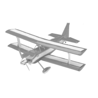
the elevator in until it is tight against the trail-
ing edge of the stabilizer. The maximum hinge
gap should be no more than 1/32”, but there
should be about a 1/16” gap between the coun-
terbalance section of the elevator and the tip
of the stabilizer. See photo # 13 below.
o 2) With the elevator tight against the sta-
bilizer, rotate the elevator down about 45º.
Apply six drops of Kwik Bond Thin C/A to
the exposed area of each hinge. Allow the
glue to cure for about ten minutes. Once cured,
the elevator may be stiff and difficult to move.
This is normal. Gently move the elevator up
and down about five to ten times to free it up.
o 3) Repeat steps # 1 and # 2 for the sec-
ond elevator half.
Photo # 13
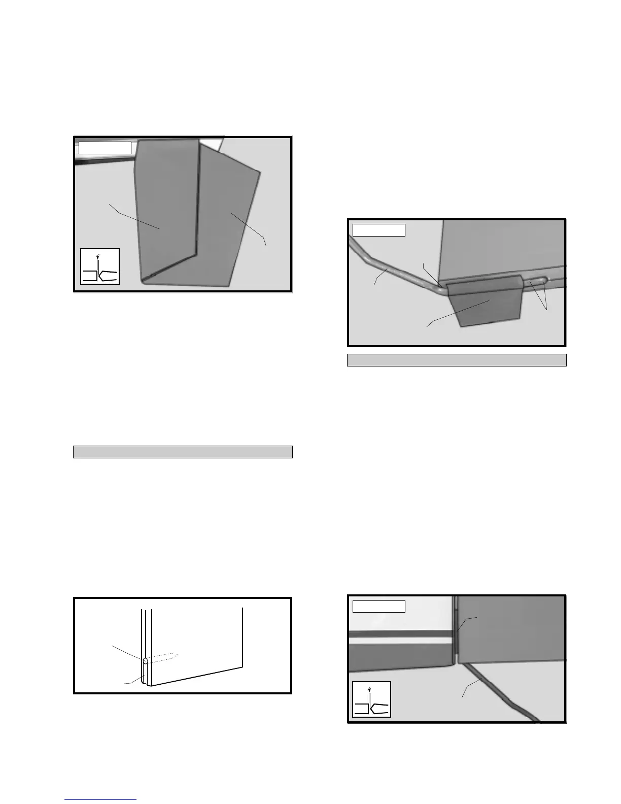
INSTALL THE TAIL WHEEL ASSEMBLY
o 4) Using a ruler, measure up from the bot-
tom of the rudder at the leading edge 1-1/8”
and place a mark.
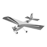
o 5) Using a 5/64” drill bit, drill a hole into
the rudder at the mark made. Using a model-
ing knife, cut a groove from the hole down to
the bottom of the rudder. Make the hole deep
enough for the tail wheel wire and the nylon
bearing to set flush in. See figure # 7 below.
Figure # 7
o 6) Apply oil or Vaseline to the hinge bear-
ing to prevent epoxy from gluing the bearing
solid to the tail wheel wire.
o 7) Mix up a small amount of Kwik Bond
5 Minute Epoxy. Apply the epoxy to only
those parts of the tail wheel wire that will be
glued to the rudder, being careful not to get
any epoxy on the nylon bearing. Pack epoxy
into the hole you drilled in the leading edge
of the rudder also.
o 8) Insert the tail wheel wire into the rudder.
Clean up any excess epoxy using a paper towel
and rubbing alcohol. See photo # 14 below.
Photo # 14
HINGE THE RUDDER
o 9) Using a modeling knife, remove the
covering from over the lower hinge slot and
nylon bearing slot precut in the back edge of
the fuselage. Use the rudder to help locate
the slots.
o 10) The C/A hinges have already been
glued into the rudder. Slide the rudder and
it's hinges, including the nylon bearing tab into
their precut hinge slots in the trailing edge of
the vertical stabilizer and lower section of the
fuselage. Slide the rudder in until it is tight
against the trailing edge of the stabilizer. The
maximum hinge gap should be no more than
1/32”. See photo # 15 below.
Photo # 15
ELEVATOR
STABILIZER
DRILL HOLE
CUT GROOVE
TAIL WHEEL
WIRE
NYLON BEARING
EPOXY
EPOXY
1/32”
1/32”
TAIL WHEEL
WIRE
NYLON
BEARING