14
o10) Hold the motor mount assembly up
to the firewall and double check that the four
intersecting lines line up with the four pre-
drilled holes in the motor mount.
The motor mount is offset to the
airplane's left side (looking from the rear)
to compensate for the right thrust built into
the firewall. Offsetting the engine will allow
the spinner to line up with cowl ring when it
is installed later.
MOUNTING THE ENGINE TO FIREWALL
o 11) Using a 1/8” drill bit, drill the mount-
ing holes through the firewall for the motor
mount.
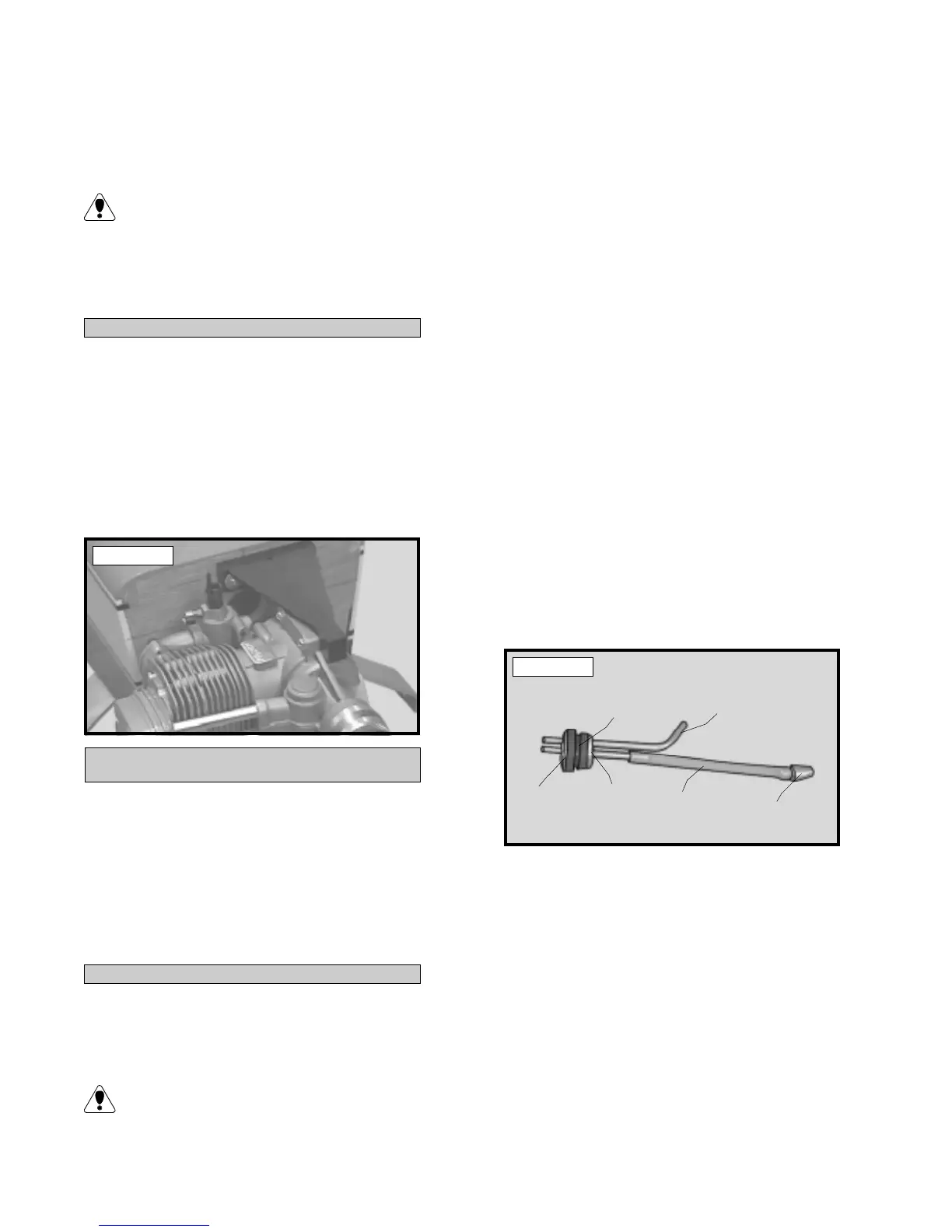
o 12) Mount the motor mount assembly to
the firewall using the four 3mm x 20mm ma-
chine screws, eight 3mm flat washers and four
3mm lock nuts. Tighten the screws and nuts
completely. See photo # 21 below.
Photo # 21
PARTS REQUIRED
FUEL TANK
FUEL TANK ASSEMBLY
o {1} Molded Fuel Tank
o {1} Rubber Stopper
o {1} 20mm Diameter Front Squash Plate
o {1} 18mm Diameter Rear Squash Plate
o {1} 3mm x 20mm Machine Screw
o {1} Weighted Metal Pick-Up
o {3} Aluminum Tubes
o {1} 90mm Silicon Fuel Tube
o 1) The fuel tank assembly incudes 3 dif-
ferent length aluminum tubes. Discard the
shortest of the three. It will not be used.
The 50mm length tube is used for the fuel
line pickup and the 80mm tube is used
for the vent/pressure line.
o 2) Using 220 grit sandpaper carefully
smooth each end of the two tubes. This will
prevent the fuel line from being cut.
o 3) Push the two aluminum tubes through
the rubber stopper until 1/2” protrudes from
the front of the stopper. Slide the 20mm di-
ameter front squash plate over the tubes at the
front of the stopper and slide the 18mm diam-
eter rear squash plate over the tubes at the rear
of the stopper. Insert the 3mm x 20mm ma-
chine screw into the center hole in the front
squash plate, then screw it through the stop-
per and into the rear squash plate. Do not com-
pletely tighten the screw at this time.
o 4) Carefully bend the longer of the two
tubes up at a 45º angle. This tube is the vent
tube. When the stopper assembly is installed
in the tank, the top of the vent tube should rest
just inside the bubble in the top of the tank.
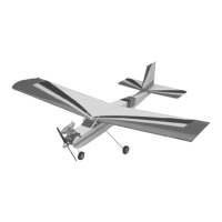
o 5) Slide the silicon fuel tubing, with the
weighted pickup attached to one end, onto the
fuel pickup tube. See photo # 22 below.
o 6) Test fit the stopper assembly into the
tank. It may be necessary to remove some of
the flashing around the tank opening using a
modeling knife. If flashing is present, make
sure none falls into the tank.
o 7) With the stopper assembly in place the
weighted pickup should be about 3/8” away
from the rear of the tank and move freely in-
side the tank. The vent tube should be inside
the bubble in the tank, but not rub against the
tank. Adjust the tubes accordingly.
Photo # 22
PICK-UP
VENT TUBE
FUEL TUBING
RUBBER
STOPPER
REAR SQUASH
PLATE
FRONT
SQUASH
PLATE