19
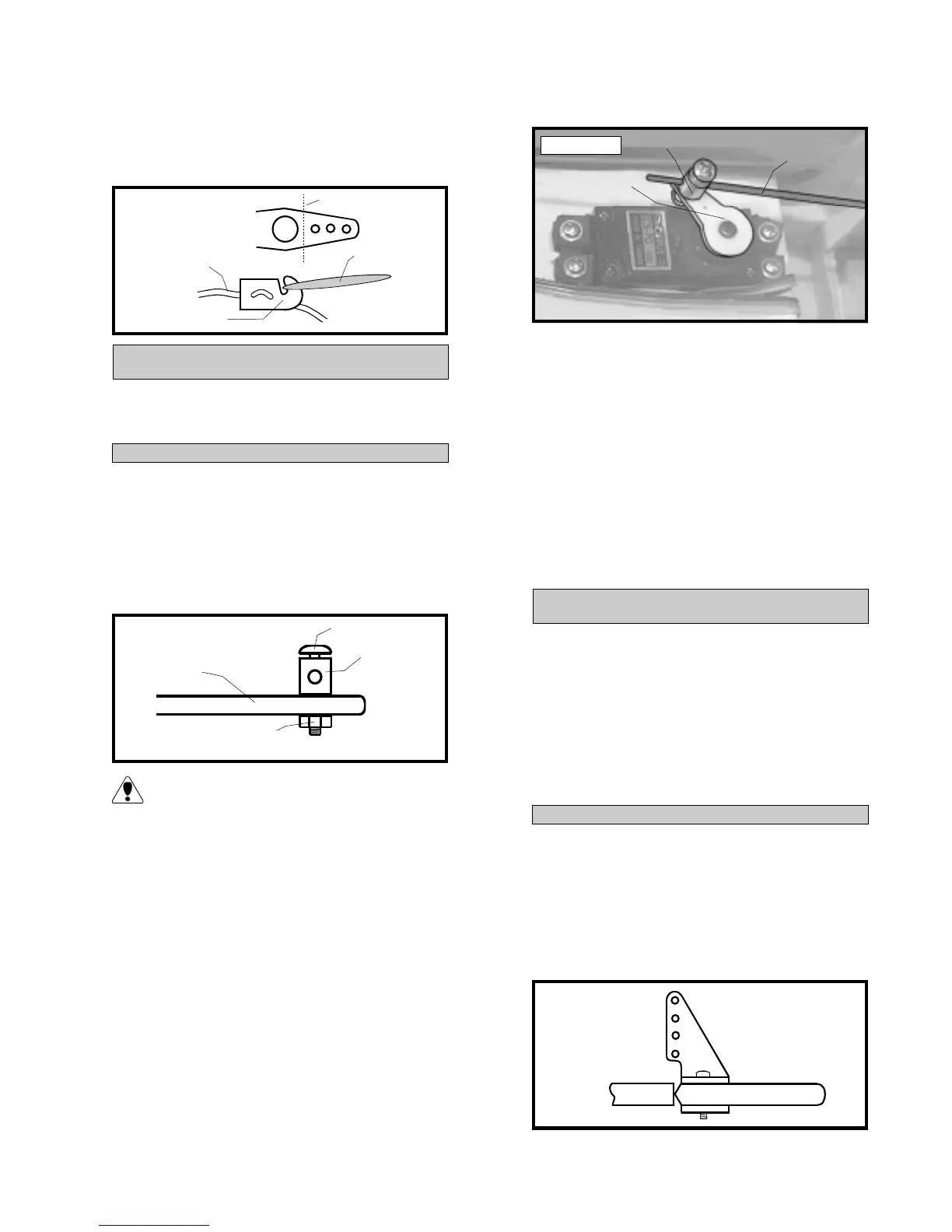
o8) Using a 1/16” drill bit, drill a hole
through the side of the fuselage for the an-
tenna to exit. Route the antenna out the fuse-
lage and secure it to the vertical fin using a
rubber band. See figure # 9 below.
Figure # 9
PARTS REQUIRED
THROTTLE LINKAGE
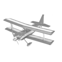
INSTALLING THE THROTTLE CONNECTOR
o {1} Adjustable Servo Connector Assembly
o 1) Install one adjustable servo connector
through the second hole out from the center
of one servo arm. You may have to enlarge
the hole in the servo arm to accommodate the
servo connector. Remove the excess material
from the servo arm using wire cutters. See
figure # 10 below.
Figure # 10
After installing the adjustable servo con-
nector apply a small drop of Kwik Bond
Thin C/A to the nut. This will prevent the
connector from loosening during flight.
o 2) Turn on the radio system. Check to
ensure that the throttle servo output shaft is
moving in the correct direction.
o 3) Slide the adjustable servo connector/
throttle arm assembly over the end of the throttle
pushrod wire. Position the throttle stick and
the throttle trim at their lowest positions.
o 4) Manually push the carburetor barrel
fully closed. Attach the servo arm to the servo
angled back about 45º from center. With the
carburetor barrel fully closed, tighten the set
screw in the adjustable servo connector.
o 5) Remove the excess throttle pushrod wire
using wire cutters. See photo # 33 below.
Photo # 33
o 6) Test the movement of the throttle
pushrod. Full forward stick and full forward
trim should result in the carburetor barrel
opening completely. Full down stick and full
forward trim should result in the approximate
idle setting. Full down stick and full down
trim should result in the carburetor barrel clos-
ing fully.
o 7) When satisfied that the pushrod link-
age is adjusted correctly and no binding is
present, install the servo arm set screw.
PARTS REQUIRED
RUDDER PUSHROD
INSTALLING THE RUDDER CONTROL HORN
o {1} Nylon Control Horn w/Nylon Back Plate
o {2} 2mm x 15mm Machine Screws
o {1} 700mm Nylon Pushrod
o {1} 2mm x 120mm Wire Threaded Both Ends
o {1} 2mm x 85mm Threaded Wire w/L-Bend
o {1} Nylon Snap Keeper
o {1} Nylon Clevis
o {1} Pushrod Support (D-32)
o 1) The centerline of the rudder control horn
is located on the left side of the rudder (looking
from behind) 1-3/8” up from the bottom of the
rudder. Position the control horn so the clevis
attachment holes are directly in-line with the
hinge line. The control horn should also be par-
allel with the hinge line. See figure # 11 below.
Figure # 11
CUT
RUBBER
BAND
MODIFIED SERVO
ARM
ANTENNA
SERVO ARM
NUT
SET SCREW
SERVO
CONNECTOR
PUSHROD
WIRE
SERVO
ARM
CONNECTOR