21
PARTS REQUIRED
ELEVATOR PUSHROD
INSTALLING THE ELEVATOR CONTROL HORNS
o {2} Nylon Control Horns w/Nylon Back Plates
o {4} 2mm x 15mm Machine Screws
o {2} 600mm Nylon Pushrods
o {2} 2mm x 100mm Wire Threaded Both Ends
o {3} Nylon Clevises (one w/1.5mm I.D. Hole)
o {1} Nylon Joiner Plate
o {2} 2.2mm x 10mm Wood Screws
o {4} 2mm Flat Washers
o {1} 2mm x 20mm Machine Screw
o {1} 2mm Hex Nut
o {1} Pushrod Support (D-32)
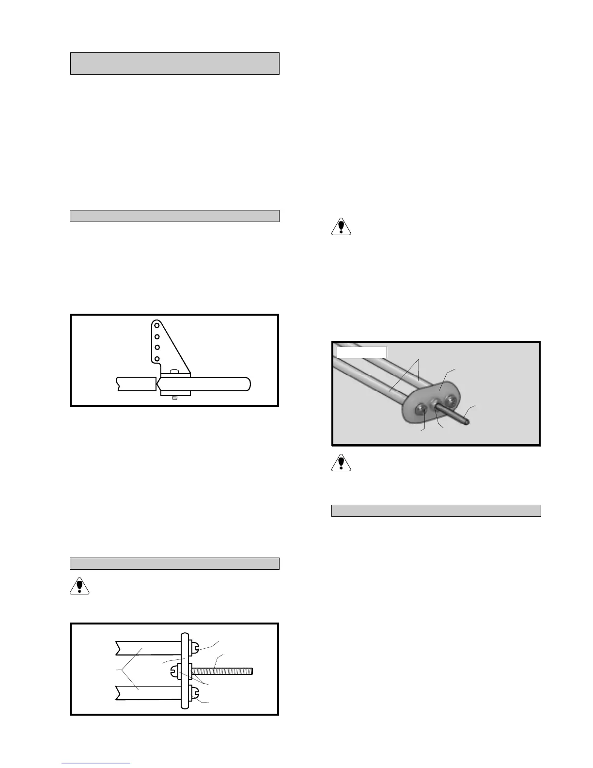
o 1) The centerline of the elevator control
horns are located on the bottom side of each
elevator half, 1” out from the fuselage sides.
Position the control horns so the clevis attach-
ment holes are directly in-line with the hinge
line. The control horns should also be parallel
with the hinge line. See figure # 12 below.
Figure # 12
o 2) When satisfied with the alignment, use
a 3/32” drill bit and the control horns as a guide
and drill the mounting holes through the el-
evator halves.
o 3) Mount the control horns to the eleva-
tor halves by inserting the 2mm x 15mm ma-
chine screws through the control horn mount-
ing bases, through each elevator half and into
the backplates. Tighten the screws, but do not
overtighten them. You do not want to crush
the wood.
INSTALLING THE PUSHROD JOINER
The elevator control system uses two
pushrods which are connected together
just before they reach the elevator servo. See
figure # 13 below.
Figure # 13
o 4) Using a 3/32” drill bit, drill a hole
through the center of the nylon joiner plate.
Slide a 2mm washer onto the 2mm x 20mm
machine screw. Slide the screw through the
center hole of the nylon joiner plate.
o 5) Slide a second 2mm washer onto the
machine screw and then thread on the 2mm
nut. Tighten the nut completely and secure it
in place using Kwik Bond Thin C/A. Let the
C/A cure completely and double check to en-
sure the screw and nut do not move.
We don't recommend using any types of
thread lock or C/A accelerators. The
chemicals in these items can destroy the ny-
lon parts.
o 6) Slide one 2mm washer over two
2.2mm x 10mm wood screws. Slide the wood
screws through the two outer holes in the ny-
lon plate and thread them into the two 600mm
nylon pushrods. See photo # 36 below.
Photo # 36
We highly recommend installing the two
wood screws using Kwik Bond 5 Minute
Epoxy to help prevent any possible chance of
them pull out during flight.
o 7) Thread one nylon clevis with 1.5mm
I.D. hole onto the end of the 2mm x 20mm
machine screw.
o 8) Using a modeling knife remove the
covering from over the two elevator pushrod
exit slots. Looking from the back of the air-
plane, the slots are located on each side of the
fuselage, 6” forward of the rudder hinge line
and 1” below the horizontal stabilizer.
o 9) Using a ruler and pen, measure for-
ward on both pushrod housings 4” from
where the pushrod housings enter the servo
compartment from the rear bulkhead.
INSTALLING THE ELEVATOR PUSHROD
PUSHROD
TUBES
2mm x 20mm
MACHINE SCREW
2mm WASHER
2.2mm x 10mm
WOOD SCREW
2mm
WASHER
NYLON
PLATE
PUSHROD
TUBES
NYLON
PLATE
MACHINE
SCREW
WOOD
SCREW
NUT