5
**SUGGESTION** To avoid scratching or damaging your new airplane, do not unwrap the pieces until
they are needed for assembly. Cover your workbench with an old towel or brown paper, both to protect
the aircraft and to protect the table. Keep a couple of jars or bowls handy to hold the small parts after you
open the bags.
**NOTE** Please trial fit all the parts. Make sure that you have the correct parts and that they fit and are
aligned properly before gluing! This will ensure proper assembly. Since the Ultimate Biplane is hand
made from natural materials, every plane is unique and minor adjustments may have to be made. How-
ever, you should find the fit superior and assembly simple.
If you should find a part missing or have questions about assembly, please call or write to the address
below:
Customer Service Center
18480 Bandilier Circle
Fountain Valley, CA. 92728
Phone: (714) 963-0329
Fax: (714) 964-6236
E-Mail: globalhobby@earthlink.net
PARTS REQUIRED
BOTTOM WING MOUNTING
ALIGN THE BOTTOM WING
o {1} Bottom Wing w/Ailerons & Hinges
o {1} Wing Bolt Doubler (W-24)
o {2} 4mm x 25mm Machine Screws
o {2} 4mm Washers
o {2} 4mm Blind Nuts
o 1) Place the wing into the wing saddle
making sure that the preinstalled dowel in the
leading edge of the wing fully engages the
predrilled hole in the forward bulkhead in the
fuselage. Push the wing as far forward as
possible. The leading edge should fit tight
against the bulkhead.
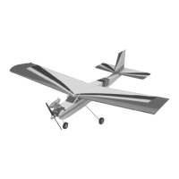
o 2) Using a ruler and pen, measure and
place a mark on the centerline of the bottom
of the fuselage at the rear of the wing saddle.
Also measure and place a mark at the
centerline of the wing at the trailing edge. See
photo # 1 below.
Photo # 1
o 3) With the wing in the wing saddle, align
the two marks and hold the wing securely in
place using a couple of pieces of masking tape.
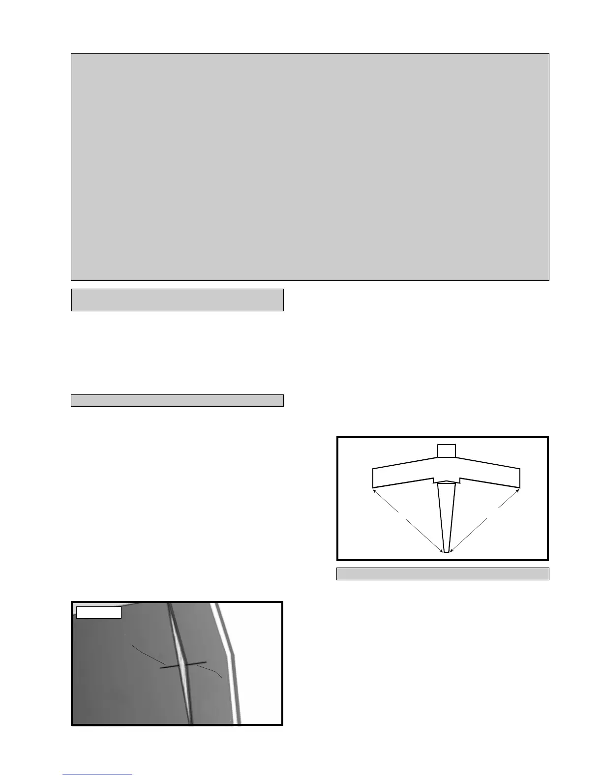
o 4) Remove the ailerons from the wing.
To double check that the wing is square to
the fuselage, use a ruler and measure from
each wing tip to the rear edge of the fuse-
lage. Both measurements should be equal.
See figure # 1 below.
Figure # 1
o 5) When satisfied with the alignment, use
a 5/32” drill bit and drill two holes through the
wing and on through the plywood wing hold
down block. The holes are located 1-1/2” out
from the centerline and 1/2” forward of the trail-
ing edge.
INSTALLING THE BLIND NUTS
A
A1
A=A1
DRAW CENTERLINE
DRAW CENTERLINE