22
o10) Using a modeling knife, cut off the
pushrod housings at this mark.
o 11) Slide the nylon pushrods into the
pushrod housings and out the exit slots.
o 12) Locate a long servo arm and using
wire cutters, remove all but one of the arms.
With the elevator servo in neutral, install the
servo arm onto the servo. The arm should be
positioned perpendicular to the fuselage sides.
o 13) Snap the clevis through the outer hole
in the servo arm.
o 14) Thread one clevis onto one end of
each 2mm x 100mm threaded wire.
o 15) Snap one clevis/wire assembly onto
each elevator control horn. Use a couple of
pieces of masking tape to hold each elevator
half in neutral.
o 16) Working with one half only, use a pen
and place a mark on the nylon elevator pushrod
where the tip of the wire overlaps it. Use a
modeling knife and cut off the nylon pushrod
5/16” behind the mark. This will leave enough
space so the threaded wire can thread into the
pushrod at least 5/16”.
o 17) Thread the wire into the pushrod.
You can thread it in further or back it out
to achieve the correct length. Repeat steps
# 14 - # 17 for the opposite side.
o 18) When satisfied with the alignment,
install the servo arm set screw and remove the
masking tape from the elevator halves. See
photo # 37 below.
Photo # 37
o 19) Move the elevator halves up and
down. There may be some flex present in
the pushrod just before it gets to the elevator
servo. If so, position one pushrod support
(D-32) between the two pushrod housings
and the servo tray. Using a small amount of
Kwik Bond 5 Minute Epoxy glue the hous-
ings to the support and the support to the tray.
PARTS REQUIRED
AILERON LINKS
INSTALLING THE CONTROL HORNS
o {4} Nylon Control Horns w/Nylon Back Plates
o {8} 2mm x 15mm Machine Screws
o {2} 2mm x 200mm Wire Threaded w/L-Bend
o {2} Nylon Clevises
o {2} Nylon Snap Keepers
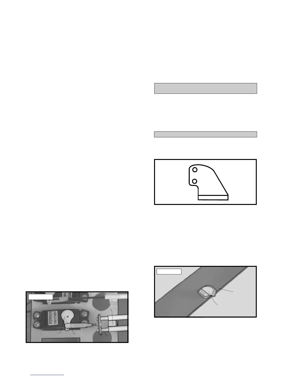
o 1) Using a modeling knife, carefully cut
the four control horns to shape. See figure #
14 below.
Figure # 14
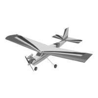
o 2) The control horns are located both on
the top and bottom ailerons. They should be
positioned 6-1/4” in from the tip of each aile-
ron. The control horns for the top wing mount
on the bottom of the ailerons and the control
horns for the bottom wing mount on the top
of the ailerons. Mount the control horns with
the clevis attachment holes facing the back of
the airplane. See photo # 38 below.
Photo # 38
o 3) When satisfied with the alignment of
all four control horns, use a 3/32” drill bit and
the control horns as a guide and drill the
mounting holes through the ailerons.
CLEVIS
SERVO
ARM
PUSHROD
SUPPORT
JOINER
ASSEMBLY
CONTROL
HORN
TRAILING
EDGE