20
o4) Thread the 2mm x 120mm threaded
wire into one end of the 700mm nylon
pushrod. For safety, thread the wire no less
than 5/16” into the pushrod.
o 5) Thread the nylon clevis onto the op-
posite end of the 2mm x 120mm threaded wire.
It should be threaded no less than 5/16” onto
the wire also.
o 6) Using a modeling knife remove the
covering from over the rudder pushrod exit
slot. Looking from the back of the airplane,
the slot is located on the left side of the fuse-
lage, 6” forward of the rudder hinge line and
1-1/4” below the horizontal stabilizer.
o 7) Insert the plain end of the nylon
pushrod into the fuselage from the back. Snap
the clevis onto the rudder control horn. Move
the rudder back and forth to ensure there is no
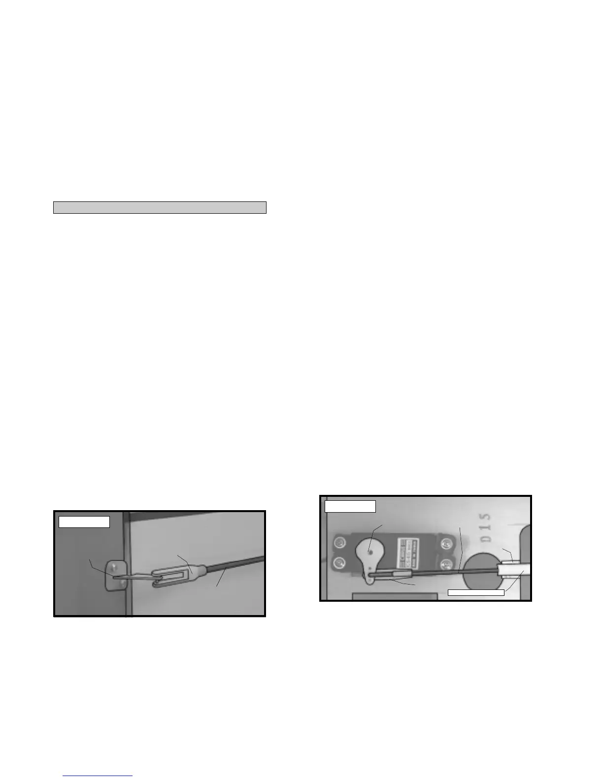
binding. See photo # 34 below.
o 2) When satisfied with the alignment, use
a 3/32” drill bit and the control horn as a guide
and drill the mounting holes through the rud-
der.
o 3) Mount the control horn to the rudder
by inserting the 2mm x 15mm machine screws
through the control horn mounting base,
through the rudder and into the backplate.
Tighten the screws, but do not overtighten
them. You do not want to crush the wood.
INSTALLING THE RUDDER PUSHROD
Photo # 34
o 8) Remove the pushrod from the pushrod
housing. Using a ruler and pen, measure for-
ward on the pushrod housing 4” from where
the pushrod housing enters the servo compart-
ment from the rear bulkhead.
o 9) Using a modeling knife, cut off the
pushrod housing at this mark.
o 10) Slide the pushrod back into the
pushrod housing. Snap the clevis onto the rud-
der control horn and use a couple of pieces of
masking tape to hold the rudder in neutral.
o 11) Locate a long servo arm and using
wire cutters, remove all but one of the arms.
Install the L-bend in the 85mm wire into the
outer hole in the servo arm. Secure the wire
in place using one nylon snap keeper.
o 12) With the rudder and rudder servo in
neutral, install the servo arm onto the servo.
The arm should be positioned perpendicular
to the fuselage sides.
o 13) Using a pen, place a mark on the ny-
lon rudder pushrod where the tip of the wire
overlaps it. Use a modeling knife and cut off
the nylon pushrod 5/16” ahead of the mark.
This will leave enough space so the threaded
wire can thread into the pushrod at least 5/16”.
o 14) Thread the wire into the pushrod.
You can thread it in further or back it out to
achieve the correct length.
o 15) When satisfied with the alignment,
install the servo arm set screw and remove the
masking tape from the rudder. See photo #
35 below.
Photo # 35
o 16) Move the rudder back and forth.
There may be some flex present in the pushrod
just before it gets to the rudder servo. If so,
glue one pushrod support (D-32) between the
pushrod housing and the servo tray using a
small amount of Kwik Bond 5 Minute Epoxy.
See photo # 35 above.
CONTROL
HORN
PUSHROD
WIRE
CLEVIS
SERVO
ARM
SNAP
KEEPER
PUSHROD
WIRE
PUSHROD
SUPPORT
PUSHROD HOUSING