73ST100 User Manual v1 Confidential & Proprietary Information
8545-0194-01 v1.0
6.2. GPS / SATELLITE ANTENNA TUNING
If the VAR wants to tune the internal GPS / satellite antenna on the PCB for a specific enclosure / environment, the following
should be used as guidance.
1. An appropriate vector network analyzer (VNA) should be used to measure return loss (S11) of the antenna. The VNA output
should be 50 ohms, and the frequency range should go up to about 3MHz but can be higher if the VNA allows. A two port
VNA is not necessary but can be used (only one port measurements will be done for antenna tuning). The VNA should
have the Port Extensions feature, which will allow for more accurate antenna tuning. In this manual, the TR5048 VNA from
Copper Mountain Technologies is used.
2. Two ST100 boards will be used for the antenna tuning: one board will be used as a calibration board, and the other board
will be used for tuning the GPS / satellite antenna.
3. The ST100 board should be placed in the plastics/enclosure where it will be used, and in an orientation that best
represents the end-application. When tuning the antenna, try not to have metallic surfaces nearby. Placing a cardboard box
under the ST100 is one way to move the antenna away from the surface it’s resting on.
4. Both ST100 boards will have hardware modifications (swapping resistors, etc.) done to it during the tuning process.
This procedure assumes that the user has some experience with soldering surface mount components (0201 inductors,
resistors).
5. On both PCBs, make sure there are no components installed on R2, R16, L13, and L14.
6. On the calibration ST100 PCB, install a 0 ohm, 0402 resistor as shown below, and connect the left pad of L21 to GND, as
shown. NOTE: Some solder mask can be scraped away on the GND plane to access GND.
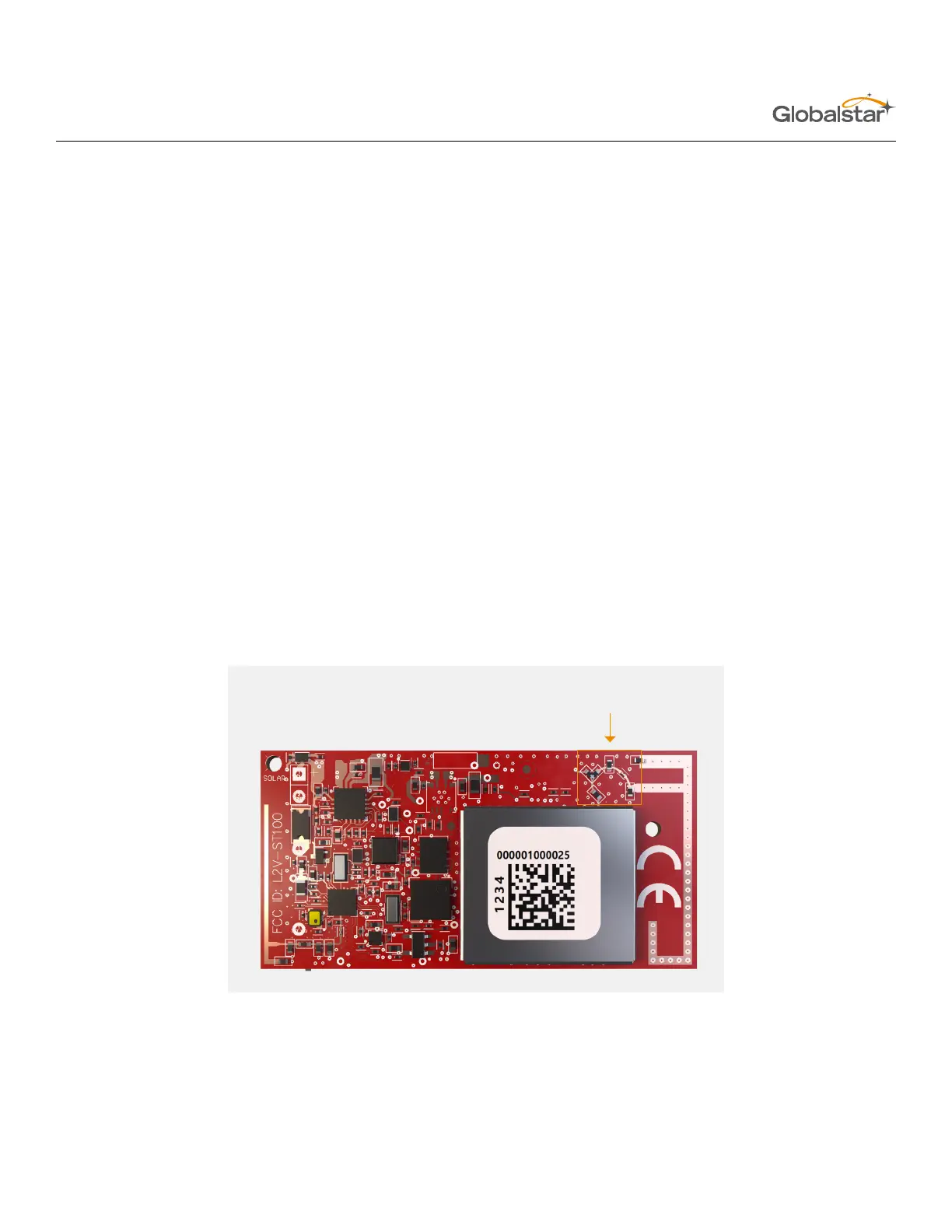
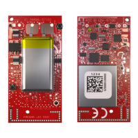
THIS IS THE AREA WHERE THE ANTENNA
MATCHING COMPONENTS ARE LOCATED.


 To Next Page