13 Servicing
13.9 Combustion Check
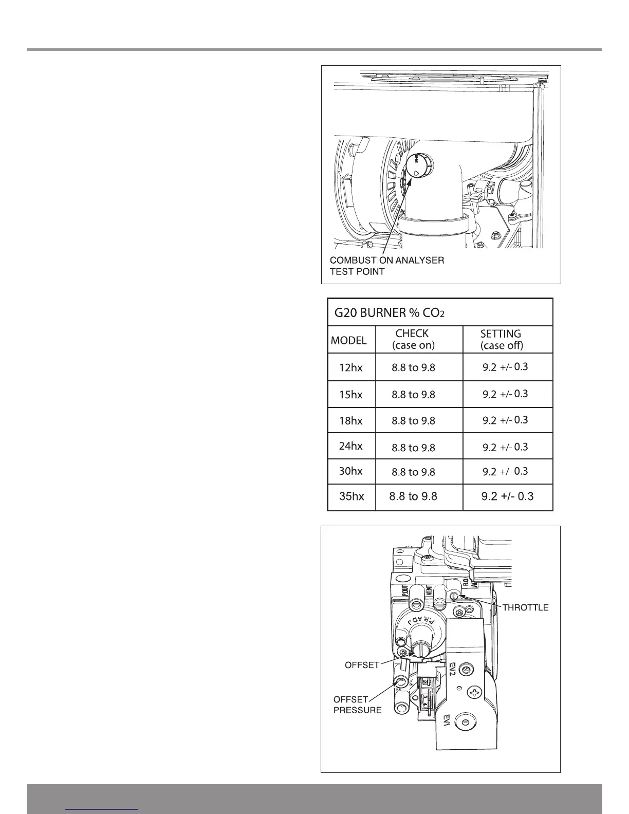
With the appliance operational connect the CO
2
combustion
analyser to the ue elbow test point or if direct rear ue tted,
the test point shown in diagram 13.12.
IMPORTANT: Remember to replace the cap on
completion of the test.
A competent person only should carry out any adjustment to
the gas valve, refer to diagram 13.13.
Monitor the combustion reading and at max
rate the reading should be 9.3% ± 0.5.
Check the burner %CO
2
at maximum rate (open a hot water
tap fully) is as shown in the “CHECK” column of the table
and if the reading falls within the tolerance, disconnect the
analyser, t the test point cap and return to functional checks
- gas rate.
If adjustment is required remove the front casing panel,
see diagram 13.1. Taking care not to touch any internal
components, proceed as follows:
Press the “reset” button on the controls fascia, release
and immediately press and hold in the “+” button. After
approximately 5 seconds “Hi” will be displayed. Pressing
the mode button when “Hi” is selected will force the boiler
to maximum rate, the display will ash between “Hi” and the
“default display” this will indicate the boiler has been forced to
maximum.
Adjust the maximum rate CO
2
with the throttle to 9.3%.
(Rotate anti-clockwise to increase).
To exit the check sequences press the “mode” and “+” buttons
simultaneously, this will reset the boiler to the default display.
Monitor the combustion reading and at min
rate the reading should be 9.3% ± 0.5.
If adjustment proves necessary then proceed as follows:
Press the “reset” button on the controls fascia, release
and immediately press and hold in the “+” button. After
approximately 5 seconds “Hi” will be displayed. Pressing the
“+” or “-” buttons will cycle between “Hi” and “Lo”. Pressing
the mode button when “Lo” is selected will force the boiler
to minimum rate, the display will ash between “Lo” and the
“default display” this will indicate the boiler has been forced to
minimum.
Refer to diagram 13.13, remove the offset screw cover.
Adjustment of the CO
2
at minimum rate is very coarse so
carefully adjust the CO
2
with the offset adjustment to 9.3%.
(Rotate clockwise to increase).
Ret the offset cover and the cap on the test point.
To exit the check sequences press the “mode” and “+” buttons
simultaneously, this will reset the boiler to the default display.
NOTE: Check the casing panel is tted correctly giving an air
tight seal.
13.10 Gas Rate Adjustment
This appliance incorporates a pre-mix burner. The gas rate
should be correct if the combustion measured in section 13.9
is correct.
13.11 Service Completion
On completion of the service the “Benchmark” Service Record
should be completed.
Diagram 13.12
13028
Diagram 13.13
12776
14290

 Loading...


