15.13 Heating Return Thermistor
For access, refer to section 15.1.
Refer to diagram 15.3.
Remove the electrical connections from the thermistor.
Remove the retaining clip from the return pipe.
Remove the thermistor from the retaining clip.
Note that the polarity of the wiring to thermistor is
unimportant.
15.14 Heat Exchanger
For access, refer to section 15.1.
Drain down the boiler heating circuit
Remove the silencer front
Pull forwards to remove.
The silencer is a push t so no tools or xings are required for
its removal or tting, see diagram 13.6.
Remove the ue hood front
Ease the securing clips away from the sump to release the
retaining catch then push the ue hood up to disengage from
the sump, see diagram 13.3.
To remove, swivel ue hood 90° and pull down and out, see
diagram 13.3.
Remove the igniter unit with support bracket
Disconnect the electrical connections and ignition lead.
Release the igniter unit support bracket.
Remove the igniter unit assembly, see diagram 13.7.
Remove the gas valve/fan
Disconnect the tubing nut at the gas valve, see diagram 13.5.
Remove the fan retaining bracket, see diagram 13.8.
To ease removal of the securing nut from the fan retaining
bracket, a at bladed screwdriver can be used in the position
shown and gently levered down as indicated.
Remove the spark electrode plug and earth connection.
Remove the fan and gas valve electrical connections.
Remove the fan and gas valve assembly.
Remove the condensate trap
Remove the drain outlet pipe from the base of the trap, see
diagram 15.1. Remove the condensate drain securing screw
and carefully pull the trap forward, see diagram 13.11.
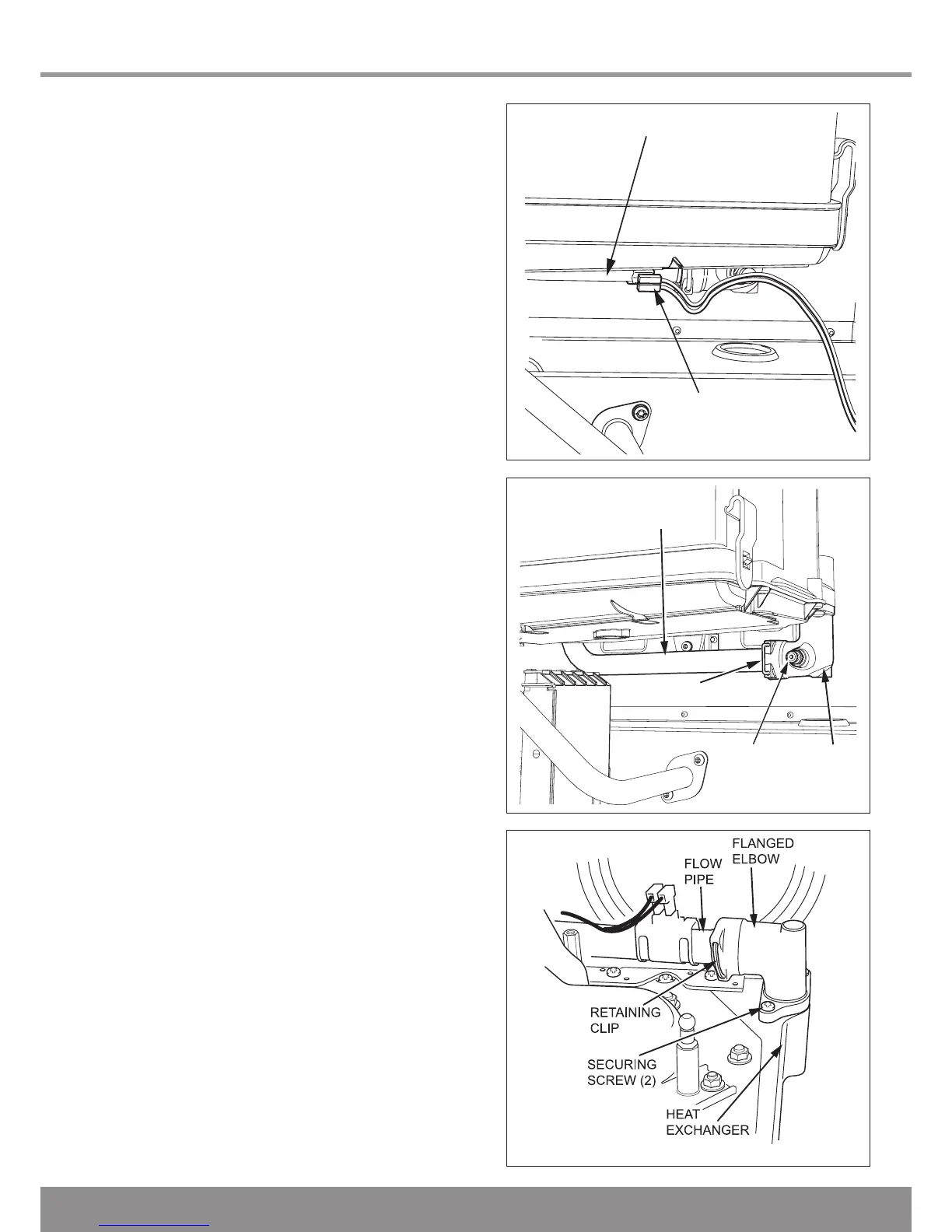
Drain the heat exchanger
Drain the heat exchanger using the drain point on the right
hand side of the heat exchanger, see diagram 15.4.

 Loading...


