15 Replacement of Parts
15.10 Burner
For access, refer to section 15.1.
Remove igniter unit, ue hood, fan and gas valve assembly
and spark electrode lead, refer to relevant sections.
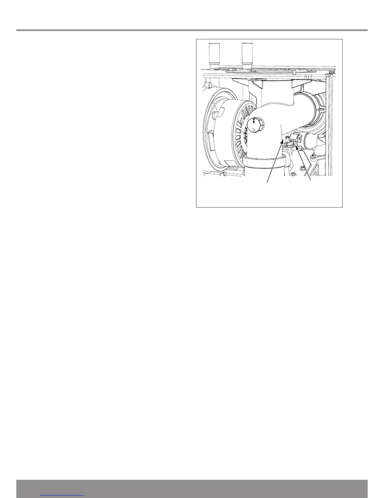
Remove the anged nuts and studs that secure the burner,
note that two studs at the rear also hold the fan clamping
bracket, see diagram 13.10.
NOTE: The burner gasket should be inspected but will not
need replacing unless there are signs of wear or damage.
IMPORTANT: Do not allow xings, nuts, screws, etc. to fall
into the open ue hood sump, use a temporary cover whilst
removing any parts.
15.11 Condensate Trap
For access, refer to section 15.1.
Remove securing screw, see diagram 13.11.
Disconnect the exible condense drain pipe from the external
plastic drain pipe beneath the boiler.
Carefully pull the condensate trap down and forward so as not
to spill its contents. The trap shoud be removed complete with
the sealing grommet and exible condensate drain pipe.
15.12 Heating Flow Thermistor
For access refer to section 15.1
Remove the silencer front, fan/gas valve assembly and ue
hood for access. See relevant sections.
Refer to diagram 15.2.
15.15 Casing Seal
Refer to Section 13.8
15.16 Access to User interface and Main PCB
For access, refer to section 15.1.
Hinge down the control box and unclip the rear cover to gain
access.
Remove electrical connections from main PCB noting their
positions for replacement.
Unclip main PCB and remove, see diagram 15.5.
Unclip user interface and remove.
For replacement, see diagram 15.6 and ensure that the user
interface connection cable is retted.
NOTE: When re-tting any of the control boards make sure
you support the control box to avoid straining hinges as you
push down and clip back into place.
Remove the electrical connections from the thermistor.
Remove the retaining clip from the ow pipe.
Remove the thermistor from the retaining clip.
Note that the polarity of the wiring to thermistors is
unimportant.

 Loading...


